Editorial Technical Reference

Busbar Processing Module

This page explains how Busbar Processing Module is classified within Electrical Equipment Manufacturing. Technical values and manufacturer relationships are research references; confirm the current specification and supplier evidence for each order.

Technical Definition & Core Assembly

A module in a switchgear assembly line that performs cutting, punching, bending, and finishing on busbars.
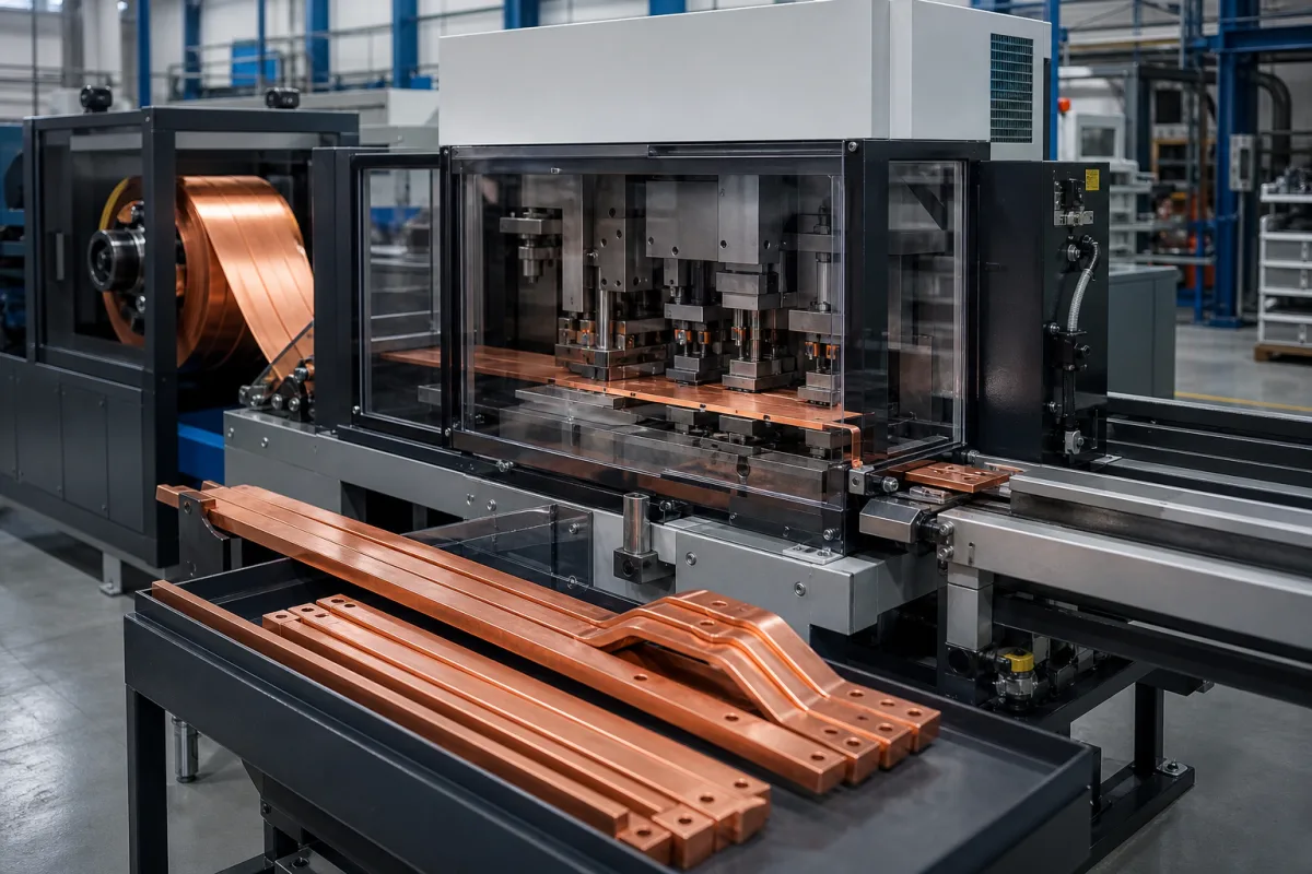
Representative product image. Confirm appearance and specifications with the manufacturer.

Product Specifications

Technical details and manufacturing context for Busbar Processing Module

Definition
The Busbar Processing Module is a component used in medium voltage switchgear assembly lines. It prepares copper or aluminum busbars for installation into switchgear panels by performing cutting, punching, bending, and finishing operations. The module automates the transformation of raw busbar stock into finished components, ensuring dimensional accuracy, correct hole patterns for connections, and required bend angles for spatial configuration within the enclosure. It is designed to handle busbars with widths ranging from 120 to 200 mm and thicknesses from 10 to 16 mm, depending on the specific model. The module operates using CNC technology, with a programmable controller guiding the sequence of operations. A feeding mechanism advances the busbar, a hydraulic or servo-driven punch creates holes, a precision shear cuts to length, and a bending unit forms angles. Sensors and measurement systems verify each step for quality control. Key parameters include cutting force (300–600 kN), punching force (200–500 kN), bending force (300–600 kN), positioning accuracy (±0.05–±0.1 mm), bending angle accuracy (±0.5–±1°), cycle time (5–15 s), rated power (5.5–15 kW), supply voltage (380–480 V AC per IEC 60038), operating temperature (-10 to 50 °C), IP rating (IP54–IP65 per IEC 60529), machine weight (1500–3000 kg), and footprint (2500×1500×1800 to 4000×2000×2200 mm). These values are reference ranges and must be confirmed for the specific model and application. The module is intended for use in industrial environments and requires proper installation and maintenance. Always verify model-specific values and standards with the legal manufacturer or supplier.
Working Principle
The module uses CNC technology. A programmable controller sequences operations: a feeding mechanism advances the busbar, a hydraulic or servo-driven punch creates holes and cutouts, a precision shear cuts the busbar to length, and a bending unit forms the busbar to specified angles. Sensors and measurement systems verify each step for quality control, ensuring dimensional accuracy and consistency.
Common Materials
Copper (Cu-ETP), Aluminum alloy (6063-T5 or similar)
Technical Parameters
ParameterTypical rangeNotes & selection driver
Max. Busbar Width120–200 mmDetermines the maximum cross-section of busbar that can be processed.
Max. Busbar Thickness10–16 mmLimits the material thickness for cutting, punching, and bending.
Cutting Force300–600 kNHigher force allows cutting thicker or harder busbar materials.
Punching Force200–500 kNDetermines the maximum hole size and thickness that can be punched.
Bending Force300–600 kNRequired for bending busbars to specified angles without deformation.
Positioning Accuracy±0.05–±0.1 mmEnsures consistent hole spacing and bend positions.
Bending Angle Accuracy±0.5–±1 °Critical for proper fit in switchgear assemblies.
Cycle Time5–15 sTime for a complete processing cycle; affects throughput.
Rated Power5.5–15 kWTotal power consumption of the module.
Supply Voltage380–480 V ACThree-phase supply; voltage range for industrial applications.IEC 60038
Operating Temperature-10–50 °CAmbient temperature range for reliable operation.
IP RatingIP54–IP65Protection against dust and water ingress.IEC 60529
Machine Weight1500–3000 kgAffects installation and floor loading requirements.
Footprint (L×W×H)2500×1500×1800 – 4000×2000×2200 mmSpace required for installation and maintenance.

Ranges are indicative industry figures for RFQ preparation, not a supplier commitment. Confirm every value and standard with the legal manufacturer before ordering.

Components / BOM
  • CNC Controller
    Programs and controls the sequence of all machining operations (feeding, punching, cutting, bending).
  • Hydraulic Punch Unit
    Applies high force to punch holes, slots, or patterns into the busbar as programmed.
  • Precision Shear
    Cuts the busbar to the exact required length with a clean, burr-minimized edge.
  • Servo Bending Unit
    Accurately bends the busbar to predefined angles using programmable servo motors.
  • Material Feeding System
    Automatically advances the busbar stock into the work area for each processing step.
  • Measurement Sensors
    Check each punch, cut and bend before the bar moves on.

Applied To / Applications

This component is essential for the following industrial systems and equipment:

Industrial Ecosystem & Supply Chain Structure

Complementary Systems
Downstream Applications
Specialized Tooling

Application Fit & Sizing Matrix

Operational Limits
pressure: 0.5 to 0.7 MPa (hydraulic system)
other spec: Busbar thickness: 3-12 mm, Busbar width: 30-200 mm, Cutting tolerance: ±0.2 mm
temperature: 5°C to 40°C (operating ambient)
Media Compatibility
✓ Copper busbars (electrolytic grade) ✓ Aluminum busbars (6061/6063 alloys) ✓ Tin-plated copper busbars
Unsuitable: Corrosive environments with high chloride/sulfur content (e.g., coastal chemical plants)
Sizing Data Required
  • Maximum busbar cross-section (width × thickness)
  • Required production rate (busbars/hour)
  • Tooling configuration (number/types of punching/bending stations)

Reliability & Engineering Risk Analysis

Failure Mode & Root Cause
Contact surface degradation
Cause: Oxidation and contamination buildup due to environmental exposure, poor sealing, or inadequate cleaning, leading to increased electrical resistance and overheating.
Mechanical joint failure
Cause: Thermal cycling stress, vibration, or improper torque during installation causing loosening of bolted connections, resulting in arcing, hot spots, or complete disconnection.
Maintenance Indicators
  • Visible discoloration, scorch marks, or melting on busbar surfaces indicating overheating
  • Audible buzzing, crackling, or popping sounds from electrical connections signaling arcing or loose joints
Engineering Tips
  • Implement regular infrared thermography inspections to detect abnormal temperature rises before catastrophic failure occurs
  • Use calibrated torque wrenches and proper joint preparation techniques during installation/maintenance, and apply anti-oxidation compound to contact surfaces

Indicative industry ranges for design and RFQ preparation. Confirm the exact figures and applicable standard with the manufacturer before specifying.

Compliance & Manufacturing Standards

Applicable Standards
IEC 61439-1:2020 - Low-voltage switchgear and controlgear assemblies ASTM B187/B187M-19 - Standard Specification for Copper, Bus Bar, Rod, and Shapes

Quoted from the published standard.

Manufacturing Precision
  • Flatness: ≤0.1mm per meter length
  • Hole diameter: ±0.05mm
Quality Inspection
  • Electrical Resistance Test
  • Dimensional Verification with CMM

Manufacturers of Busbar Processing Module

Manufacturer profiles associated with Busbar Processing Module.

Sourcing Busbar Processing Module from China?
Tell us your specification and target quantity — we will match it against manufacturer records and come back with the factories that fit.
Request manufacturers We manufacture this

Manufacturer listings support early research and capability understanding. They are not certification, ranking, or transaction guarantees.

Technical documentation
Request current drawings, revision history, and a signed specification sheet.
Manufacturing capability
Verify equipment lists, process limits, capacity, and representative production evidence.
Inspection readiness
Confirm test methods, calibrated equipment, sampling plans, and traceable reports.
Supplier transparency
Check the legal entity, factory address, ownership, certifications, and direct contacts.

CNFX does not score or rank suppliers. Buyers must verify all claims and documents with the legal manufacturer before ordering.

Supply Chain Compatible Machinery & Devices

Circuit Breaker Arc Chute

The Circuit Breaker Arc Chute is a critical safety component in electrical circuit breakers, designed to rapidly extinguish electric arcs that form during circuit interruption.

Explore Specs →
Medium Voltage Switchgear Assembly Line

Automated production system for assembling medium voltage electrical switchgear.

Explore Specs →
Motor Terminal Block

A motor terminal block is a standardized electrical component that provides secure, insulated connection points for motor winding leads.

Explore Specs →
PLC Control System

A digital industrial computer control system that monitors inputs, makes decisions based on a custom program, and controls outputs to automate industrial processes.

Explore Specs →

Frequently Asked Questions

What materials can the Busbar Processing Module handle?

The module is designed to process copper (Cu-ETP) and aluminum alloy (6063-T5 or similar) busbars, as listed in the product specifications.

What is the maximum busbar width and thickness it can process?

The maximum busbar width ranges from 120 to 200 mm, and the maximum thickness ranges from 10 to 16 mm, depending on the specific model. Confirm exact values with the manufacturer.

What is the positioning accuracy of the module?

The positioning accuracy is ±0.05 to ±0.1 mm, ensuring consistent hole spacing and bend positions. This is a reference range; verify for the specific model.

What are the electrical requirements?

The module requires a three-phase supply voltage of 380–480 V AC, per IEC 60038. The rated power is 5.5–15 kW. Always check the nameplate and consult the manufacturer for exact requirements.

Data Basis

Editorial classification, named public sources where available, and source-reviewed manufacturer records.

Preliminary Technical Classification
This page supports structured research, RFQ preparation, and supplier evaluation. It does not replace buyer-led supplier qualification, standards review, or technical approval.
Buyer enquiry

Request manufacturing insight for Busbar Processing Module

Ask for use case, specification boundaries, supplier type, and RFQ preparation information for this product.

Where it goes
Straight to the CNFX editorial desk, and to the manufacturer if this product is linked to a claimed profile. Nothing is broadcast to a supplier list.
Your details stay here
We do not sell or rent enquiry data, and we do not add you to a mailing list. Used only to answer this request.
No commission, no middleman
CNFX is a directory. We take no cut of any order and never negotiate on a supplier's behalf.
What we don't claim
A listing is not an endorsement. Qualify every supplier and verify every figure yourself before ordering.

Your business information is used only to process this request.

Thank you! Your message has been sent. We'll respond within 1–3 business days.
Sorry, we couldn't send your message. Please try again, or email us at contact@cnfx.com.

Need to Manufacture Busbar Processing Module?

Compare manufacturer profiles with relevant product and process capability.

Previous Product
Wire Tensioning System
Last Product
Get QuotesChat