Editorial Technical Reference

Measurement Module

This page explains how Measurement Module is classified within Electrical Equipment Manufacturing. Technical values and manufacturer relationships are research references; confirm the current specification and supplier evidence for each order.

Technical Definition & Core Assembly

A specialized electronic component within an Industrial Power Distribution Test Bench designed to accurately measure, monitor, and record electrical parameters.
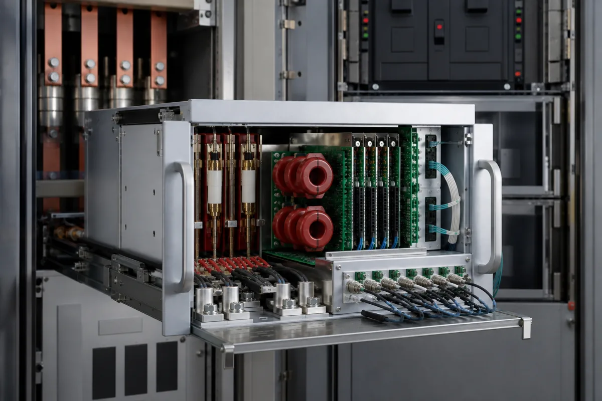
Measurement Module in a manufacturing environment
Representative product image. Confirm appearance and specifications with the manufacturer.

Product Specifications

Technical details and manufacturing context for Measurement Module

Definition
The Measurement Module is a critical sub-assembly of an Industrial Power Distribution Test Bench. Its primary role is to provide precise, real-time data acquisition for electrical characteristics such as voltage, current, power (active, reactive, apparent), power factor, frequency, and harmonic distortion. It interfaces with sensors and transducers, conditions the signals, and converts them into digital data for analysis, display, and logging by the test bench's control system, enabling performance validation, efficiency testing, and fault diagnosis of power distribution equipment. The module is designed for integration into test benches used in electrical equipment manufacturing, where accurate measurement is essential for quality assurance and compliance testing. It supports a measurement accuracy of ±0.5% for voltage and current, with higher accuracy available on request, in accordance with IEC 61557-12. The input voltage range is 0–600 V AC/DC, with CAT III rating and overvoltage protection up to 720 V. The input current range is 0–10 A for direct measurement, with external current transformers for higher currents. The frequency range is 45–65 Hz, suitable for 50/60 Hz power systems. The sampling rate is 10–20 kS/s per channel, enabling harmonic analysis up to the 40th harmonic. The module operates within a temperature range of -10 to 55 °C (extended -20 to 70 °C optional) and can be stored at -40 to 85 °C, per IEC 60068-2-1 and IEC 60068-2-2. It withstands humidity from 5 to 95% RH (non-condensing) per IEC 60068-2-78. Ingress protection is IP54 for portable and IP65 for panel mount, per IEC 60529. Power supply is 9–36 V DC, reverse polarity protected with isolated DC/DC converter, and power consumption is ≤5 W (typical 3 W). Communication interfaces include RS485 and Modbus RTU, with optional Ethernet/IP, per IEC 62056-21. Weight ranges from 0.5 to 1.5 kg depending on enclosure and options. The module is constructed with a printed circuit board, semiconductors (ICs, ADC, microcontroller), precision resistors and capacitors, and connectors (terminal blocks, communication ports). For specific applications, verify model-specific values and standards with the legal manufacturer or supplier.
Working Principle
The module operates by receiving low-level analog signals (e.g., mV, mA) from current transformers (CTs), potential transformers (PTs), or other sensors connected to the test circuit. These signals are passed through signal conditioning circuits (amplification, filtering, isolation) to ensure accuracy and safety. An Analog-to-Digital Converter (ADC) then digitizes the conditioned signals. A microcontroller or Digital Signal Processor (DSP) processes this digital data, applying calibration factors and performing calculations (like RMS, power computations) to derive the final measurement values, which are then communicated via standard protocols (e.g., Modbus, Ethernet) to the main controller.
Common Materials
Printed Circuit Board (PCB), Semiconductors (ICs, ADC, microcontroller), Precision Resistors & Capacitors, Connectors (terminal blocks, communication ports)
Technical Parameters
ParameterTypical rangeNotes & selection driver
Measurement Accuracy±0.5 %For voltage and current; higher accuracy available on requestIEC 61557-12
Input Voltage Range0–600 V AC/DCCAT III rated; overvoltage protection up to 720 V
Input Current Range0–10 ADirect measurement; external CTs for higher currents
Frequency Range45–65 HzSuitable for 50/60 Hz power systems
Sampling Rate10–20 kS/sPer channel; enables harmonic analysis up to 40th
Operating Temperature-10–55 °CExtended range -20–70 °C optionalIEC 60068-2-1, IEC 60068-2-2
Storage Temperature-40–85 °CNon-operatingIEC 60068-2-1, IEC 60068-2-2
Humidity Range5–95 % RHNon-condensingIEC 60068-2-78
Ingress ProtectionIP54–IP65IP65 for panel mount; IP54 for portableIEC 60529
Power Supply9–36 V DCReverse polarity protected; isolated DC/DC
Power Consumption≤5 WTypical 3 W
Communication InterfaceRS485, Modbus RTUOptional Ethernet/IPIEC 62056-21
Weight0.5–1.5 kgDepends on enclosure and options

Ranges are indicative industry figures for RFQ preparation, not a supplier commitment. Confirm every value and standard with the legal manufacturer before ordering.

Components / BOM
  • Signal Conditioning Circuit
    Amplifies, filters, and isolates raw sensor signals to protect downstream electronics and improve signal quality for accurate digitization.
    Material: PCB with precision passive components (resistors, capacitors, operational amplifiers)
  • Analog-to-Digital Converter (ADC)
    Converts the conditioned analog voltage/current signals into discrete digital values for processing by the microcontroller.
    Material: Semiconductor IC
  • Microcontroller / DSP Unit
    The computational core that processes digital data, performs measurement calculations (RMS, power, harmonics), manages communication, and executes firmware.
    Material: Semiconductor IC
  • Communication Interface
    Provides the physical and protocol layer (e.g., RS-485, Ethernet port) to transmit measurement data to the test bench's central controller or HMI.
    Material: Connectors, transceiver ICs, magnetics
  • Power Supply Unit
    Converts the bench's input power to stable, low-voltage DC levels required by the module's internal electronics.
    Material: PCB with voltage regulators, transformers/isolators, capacitors

Applied To / Applications

This component is essential for the following industrial systems and equipment:

Industrial Ecosystem & Supply Chain Structure

Complementary Systems
Downstream Applications
Specialized Tooling

Application Fit & Sizing Matrix

Operational Limits
pressure: Atmospheric only (non-pressurized enclosure)
other spec: Voltage Range: 0-1000V AC/DC, Current Range: 0-100A, Frequency: 45-65Hz, Accuracy: ±0.1% of reading
temperature: -10°C to +55°C (operating), -40°C to +85°C (storage)
Media Compatibility
✓ Clean dry air environments ✓ Non-corrosive industrial atmospheres ✓ Indoor climate-controlled facilities
Unsuitable: High humidity, conductive dust, or corrosive gas environments
Sizing Data Required
  • Maximum voltage to be measured (V)
  • Maximum current to be measured (A)
  • Required measurement accuracy and sampling rate

Reliability & Engineering Risk Analysis

Failure Mode & Root Cause
Sensor Drift
Cause: Environmental contamination (dust, moisture, chemicals) affecting sensing elements, or electronic component aging leading to calibration loss.
Signal Interruption
Cause: Physical damage to wiring or connectors from vibration, corrosion, or improper installation, or internal circuit board failure due to thermal stress or power surges.
Maintenance Indicators
  • Erratic or inconsistent readings compared to known reference values
  • Complete loss of output signal or communication failure with the control system
Engineering Tips
  • Implement regular calibration schedules using traceable standards and maintain environmental seals to prevent contamination ingress
  • Use vibration-resistant mounting, proper cable management with strain relief, and install surge protection on power and signal lines

Indicative industry ranges for design and RFQ preparation. Confirm the exact figures and applicable standard with the manufacturer before specifying.

Compliance & Manufacturing Standards

Applicable Standards
CE Marking (EU Machinery Directive 2006/42/EC)

Quoted from the published standard.

Manufacturing Precision
  • Linear Measurement Accuracy: +/-0.005 mm
  • Repeatability: +/-0.002 mm
Quality Inspection
  • Calibration Verification against NIST-traceable Standards
  • Environmental Stability Testing (Temperature/Humidity)

Manufacturers of Measurement Module

1 company lists this product among what they make. Company figures are quoted from each company's own website; every card states where the relationship came from.

Chengdu JRT Meter Technology Co., Ltd.
Chengdu, Sichuan, CN
Listed on the company's own website · profile compiled by CNFX from public sources
Listed there as: “Tof Laser Measurement Module”
View source page ↗ jrt-measure.com · checked 2026-09-09

Manufacturer listings support early research and capability understanding. They are not certification, ranking, or transaction guarantees.

Share this page
Technical documentation
Request current drawings, revision history, and a signed specification sheet.
Manufacturing capability
Verify equipment lists, process limits, capacity, and representative production evidence.
Inspection readiness
Confirm test methods, calibrated equipment, sampling plans, and traceable reports.
Supplier transparency
Check the legal entity, factory address, ownership, certifications, and direct contacts.

CNFX does not score or rank suppliers. Buyers must verify all claims and documents with the legal manufacturer before ordering.

Supply Chain Compatible Machinery & Devices

Motor Terminal Block

A motor terminal block is a standardized electrical component that provides secure, insulated connection points for motor winding leads.

Explore Specs →
PLC Control System

A digital industrial computer control system that monitors inputs, makes decisions based on a custom program, and controls outputs to automate industrial processes.

Explore Specs →
Control Panel

A centralized interface for monitoring and controlling industrial equipment and processes

Explore Specs →
PLC Control Panel

A centralized interface unit housing the programmable logic controller and associated control components for industrial automation systems.

Explore Specs →

Frequently Asked Questions

What electrical parameters can the measurement module measure?

It measures voltage, current, active/reactive/apparent power, power factor, frequency, and harmonic distortion up to the 40th harmonic, depending on configuration.

What is the accuracy of the measurement module?

The standard accuracy is ±0.5% for voltage and current, per IEC 61557-12. Higher accuracy may be available on request; confirm with the manufacturer.

What communication interfaces does the module support?

It supports RS485 and Modbus RTU as standard, with optional Ethernet/IP. All interfaces comply with IEC 62056-21.

What are the environmental limits for operation?

Operating temperature is -10 to 55 °C (optional -20 to 70 °C), storage -40 to 85 °C, humidity 5-95% RH non-condensing, and ingress protection IP54 (portable) or IP65 (panel mount).

Data Basis

Editorial classification, named public sources where available, and source-reviewed manufacturer records.

Preliminary Technical Classification
This page supports structured research, RFQ preparation, and supplier evaluation. It does not replace buyer-led supplier qualification, standards review, or technical approval.
Buyer enquiry

Request manufacturing insight for Measurement Module

Ask for use case, specification boundaries, supplier type, and RFQ preparation information for this product.

Where it goes
Straight to the CNFX editorial desk, and to the manufacturer if this product is linked to a claimed profile. Nothing is broadcast to a supplier list.
Your details stay here
We do not sell or rent enquiry data, and we do not add you to a mailing list. Used only to answer this request.
No commission, no middleman
CNFX is a directory. We take no cut of any order and never negotiate on a supplier's behalf.
What we don't claim
A listing is not an endorsement. Qualify every supplier and verify every figure yourself before ordering.

Your business information is used only to process this request.

Thank you! Your message has been sent. We'll respond within 1–3 business days.
Sorry, we couldn't send your message. Please try again, or email us at [email protected].

Need to Manufacture Measurement Module?

Compare manufacturer profiles with relevant product and process capability.

Previous Product
Wire Tensioning System
Last Product
Get QuotesChat