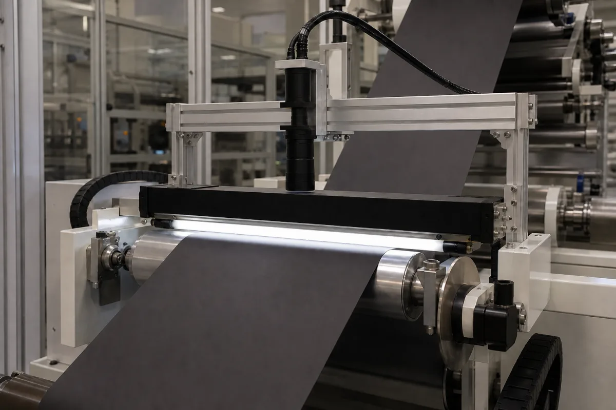
Line-scan inspection of coated battery electrode web
In the illustration a camera on an aluminium gantry looks down at a dark coated electrode web as it wraps a roller, lit by a bar light across the full width. That is the shape of in-line electrode inspection between coating, calendering and slitting. The camera only sees what the light, the pixel size and the line timing allow, so this page starts from the defects and works back to those three settings.
Covers in-line camera inspection of coated lithium-ion battery electrode web during coating, calendering and slitting: target defects and how they form, lighting for dark carbon-containing coatings, line-scan pixel size and line rate against web speed, encoder-driven line triggering, slit-edge burr and width checks, and classifier performance figures. Camera-based inspection, measurement and guidance for production lines, with cameras, lenses and lighting, are on Machine vision system; casting inspection cells are on Vision system for cast and machined parts; synchronised GigE camera arrays and vision controllers have their own pages. Knife settings that prevent burrs are on Battery electrode slitting machine, and the coater and dryer on Lithium-ion battery electrode coating machine.
CNFX editorial research · Sources checked October 12, 2026 · 4 sources
The iScience review of gigafactory equipment (2025) lists agglomerates, pinholes, metal particle contaminants and nonuniform coating as coating-stage problems, and names beta transmission and CCD camera inspection as the technologies used in industry to detect them.
Argonne's CoatingVision dataset (Scientific Data, 2026) holds over 2,200 labelled slot-die coating images in four classes: surface cracks, delamination cracks, pinholes and unclassified defects. It was built to train and benchmark detection models, which is also how a buyer can ask a supplier to prove its classifier.
Defect
How it forms (source)
Seen by
Surface crack
Solvent evaporation pulls particles together; as pores empty, cohesion weakens and cracks start at the top layer and grow toward the substrate (Argonne). Larger particles, wider size distribution, thicker coatings and high drying temperature raise the risk
Camera
Delamination crack
Adhesion between coating and substrate too low for the drying stresses; depends on binder, substrate roughness and stress (Argonne)
Camera
Pinhole
Listed with cracks and delamination in the Argonne dataset and among coating defects in the iScience review
Camera
Agglomerate, metal particle
Listed as coating defects in the iScience review
Camera
Nonuniform coating
Listed in the iScience review; areal loading variation
Beta transmission gauge alongside the camera
Ask which defect classes the system reports separately, the smallest size of each it is specified to detect, and whether coating weight is measured by a separate gauge.
02
Lighting a near-black coating
Graphite and carbon-black-filled coatings return little light, which shapes the optics before any software is chosen.
When Argonne imaged its coatings, the light-absorbing carbon black meant the shutter time had to be lengthened for enough exposure and the camera sensitivity set to its highest value, with LED lamps on both sides of the camera to reduce shadows. Those were static samples under an area camera. On a moving web, a longer exposure smears the image along the direction of travel, so the light has to supply the missing signal instead.
That is why the illustration shows a bright bar light running the full web width right under the camera line: the illuminated stripe only needs to be as long as the web is wide and a few lines deep.
The moving-web consequence is editorial reasoning from the static-sample finding. Ask for the light type, its intensity at the web and whether exposure is fixed or tracks web speed.
03
Pixel size, line rate and encoder sync
A line-scan camera builds the image one row at a time as the web passes, so down-web resolution depends on timing, not on the sensor.
Euresys defines the terms: cross-web pixel pitch is fixed by the sensor and optics, while down-web line pitch is web speed divided by line rate. Euresys says that in all but a small share of cases the application wants a constant, preferably square (1:1), pixel aspect ratio. With a varying web speed that means a motion encoder whose pulses are converted in real time into camera triggers at a proportional rate, by an integer divider or by a multiplier/divider that accepts any ratio from 0.001 to 1000 with better than 0.1% accuracy.
1st Vision gives the rate formula as line frequency = web speed / object-space size of one pixel, with a worked example of a 550 mm field on a 2,000-pixel sensor: 0.275 mm per pixel and 4,000 mm/s give about 14.5 kHz. Too slow a rate blurs or skips slices; too fast oversamples, so one feature can read as two. The system must keep imaging during ramp-up and slow-down, which is the case an encoder handles and a fixed rate does not.
Case
Web speed
Pixel size
Line rate needed
8-bit data rate
1st Vision example
4,000 mm/s
550 mm / 2,000 px = 0.275 mm
≈14.5 kHz
≈29 MB/s
Electrode web at 100 m/min (assumed 400 mm field, 8,192 px)
≈1,667 mm/s
≈0.049 mm
≈34 kHz
≈280 MB/s
Same optics at 25–50 m/min
≈417–833 mm/s
≈0.049 mm
≈8.5–17 kHz
≈70–140 MB/s
Editorial calculation. The 100 m/min figure is the slitting rewind speed the iScience review cites as desirable and 25–50 m/min its drying-line range; the 400 mm field and 8,192-pixel sensor are assumptions. 1st Vision labels 0.275 as "pixels per mm"; the arithmetic is millimetres per pixel.
04
Slit edges: burr and width
The iScience review sets out the slitting targets: a slitting error tolerance of 0.1 mm at a rewind speed of 100 m/min, and burr edges below 10 µm as the aim of current development. Preventing the burr is a slitter question; this section is about whether a camera can see it.
Those two numbers sit at very different scales. A 0.1 mm width tolerance is about two pixels at the ≈0.049 mm pixel in the table above, workable for a full-width camera with sub-pixel edge finding. A 10 µm burr is about one-fifth of one such pixel (Editorial calculation), so a full-width surface camera cannot measure it; burr checks need separate high-magnification edge optics or an offline method.
Ask whether width and burr are measured on every lane, the pixel size of the edge cameras, and how a failing lane is marked or traced to a knife position.
05
What to give a supplier of electrode inspection
Paste it into your enquiry below or into an email to a maker, then replace every bracket.
State the electrode type (anode or cathode, coating colour), web width and number of lanes, line speed range including ramps, where the station sits (after coating, after calendering, at the slitter), the defect classes and smallest sizes to detect, and the width and burr tolerances. Ask for the camera pixel count and object pixel size, maximum line rate and how it is synchronised to an encoder, the lighting design, the data rate and storage, defect-map output and marking, and validation figures (precision and recall per class) on your own samples.
2 companies list this product among what they make. Company figures are quoted from each
company's own website; every card states where the relationship came from.
Aurora Deep Vision
TBC
Aurora Deep Vision's site lists AI vision inspection systems and in-line quality control for tyre and rubber processing, including material strip dimension measurement and belt layer defect detection.
Top Vision's site lists machine vision inspection systems and automated optical inspection machines, with surface inspection and precision measurement among its applications.
Explore company information and manufacturing capabilities, then discuss the scope of your project with a relevant supplier.
Share this page
Compiled and source-reviewed by the CNFX editorial team.
Each manufacturer above links to the page on that company's own website where the product is listed, with the date we checked it. How we source and review
· Page last updated 13 October 2026
Buyer questions
What defects does electrode coating inspection look for?
The iScience review lists agglomerates, pinholes, metal particle contaminants and nonuniform coating, and Argonne's dataset labels surface cracks, delamination cracks and pinholes. [1][2]
How is the line rate of a line-scan camera chosen?
Line rate = web speed / object-space pixel size. 1st Vision's example: 0.275 mm per pixel at 4,000 mm/s needs about 14.5 kHz. [4]
Why use an encoder rather than a fixed line rate?
Euresys explains that a constant pixel aspect ratio on a web of varying speed needs camera triggers proportional to encoder pulses, by a divider or a multiplier/divider. [3]
How well do defect classifiers perform on electrode coatings?
On Argonne's dataset the best of three models (EfficientNet) reached F1 0.913 for surface cracks, 0.828 for pinholes and 0.754 for delamination; pinhole recall was 0.751. [2]
Sources and what still needs a direct check
Sources checked 2026-10-12. A peer-reviewed review of battery manufacturing equipment, a national-laboratory defect dataset, a frame-grabber maker's line-scan guide and a camera distributor's line-rate note.