Keeping a press brake backgauge where the CNC says it is
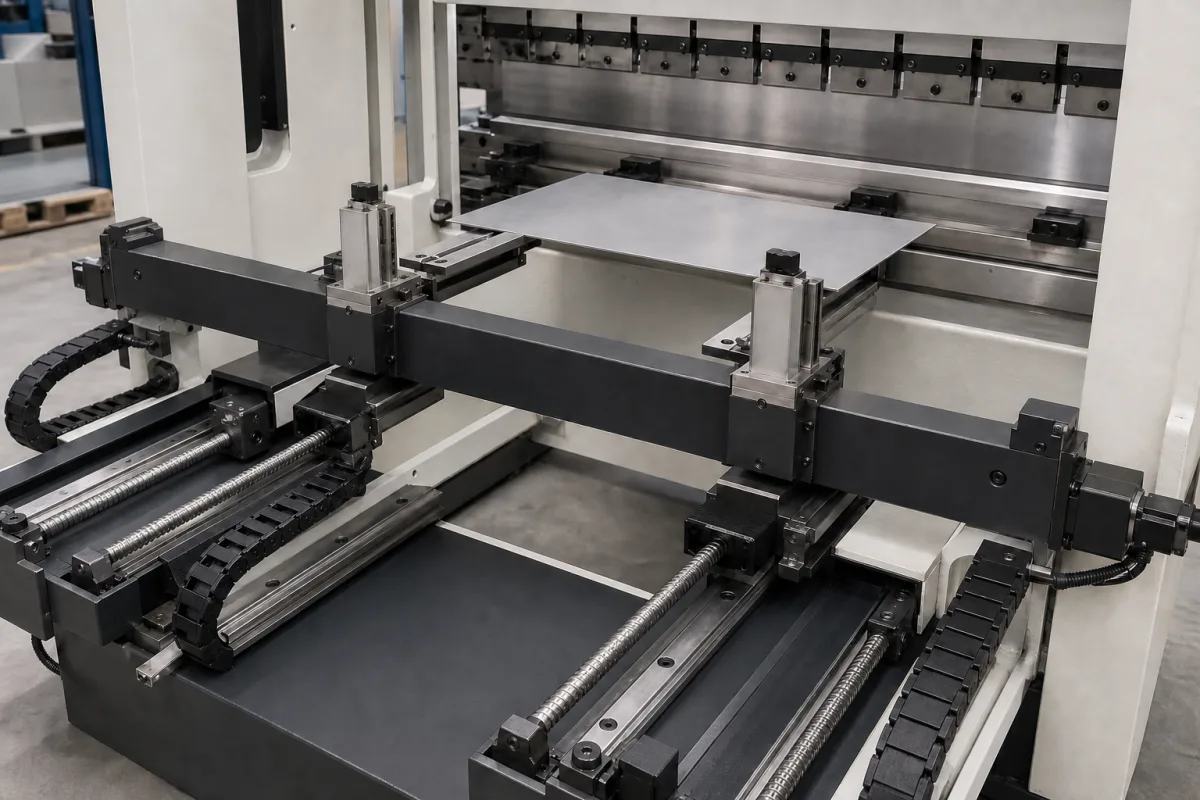
The illustrated backgauge is a crossbar with two finger blocks, driven front to back on ball screws and linear guides at each side, with drag chains for the cables. When it is new it puts the sheet edge where the CNC says. Over months, guide contamination, screw wear, a finger collision or a loose coupling move it away from that. Durmapress and ADH Machine Tool both publish service guides for this stage of the machine's life, and they agree on one thing: measure how the error behaves before changing any offset.
Covers keeping a press brake backgauge accurate in service: reading error patterns along the X travel, mechanical, servo, encoder and parameter causes, calibration steps and intervals, alignment of the backstop bar to the ram, and routine maintenance of ball screws, guides and fingers. Choosing backgauge axes and per-axis accuracy at purchase is on Press Brake Back Gauge (1386); gauging methods and finger inserts on Back Gauge Gauging Methods (3025); in-process angle measurement on CNC Press Brake (3068).
CNFX editorial research · Sources checked October 13, 2026 · 4 sources
Read the error before touching the offset: four patterns and what each points to
Durmapress's positioning troubleshooting guide asks for the error to be measured at more than one travel position before any program or offset is edited, because a software offset can hide a local mechanical fault and make another job inaccurate once the part is repaired.
The table turns a vague complaint, flange lengths are off, into a test plan: gauge the same target at the front, middle and rear of the travel, and approach one target from both directions. Durmapress also notes that repeated manual offsets on parts needing independent finger support can be a configuration limit of the backgauge rather than a calibration fault.
Its general troubleshooting table adds the electrical side: a servo alarm points to overload, overheating or an encoder feedback fault; an encoder fault to damage, a loose cable or contamination; slow movement to drive parameters, binding or overload.
Error pattern (Durmapress)
More likely cause (Durmapress's heading)
First place to inspect
Uniform: same offset at front, middle and rear
Reference offset or a mispositioned backgauge beam
Home reference, beam squareness, CNC compensation
Progressive: error grows or shrinks along X
Rail misalignment, ball-screw wear, backlash or a twisted mounting path
Full X travel, guides and transmission
Spot-specific: large at one position, smaller elsewhere
Damaged finger block, worn bearing section, damaged guide or local obstruction
That position on the travel
Direction-dependent: changes with approach direction
Backlash, loose couplings, worn thrust bearings or ball screw
Ball screw, coupling, thrust bearing, drive nut
Left and right fingers disagree
Finger alignment, Z-axis or beam squareness
Finger blocks, beam, Z movement
Display stable, finger not
Mechanical play
Mounting, bearings, guides, transmission
Display and finger both jump
Encoder, cable, drive or electrical fault
Feedback cable, connector, encoder, drive
Parts shift only during forming
Material movement or tooling condition
Sheet contact, die shoulders, tooling seating
The pattern-to-cause mapping is Durmapress's diagnostic guidance; confirm with the machine builder's service manual.
02
Calibration: clean, measure, check parallelism, square the fingers, then bend
Durmapress's back gauge guide gives a five-step calibration; ADH Machine Tool's press brake calibration guide places the backgauge step after ram parallelism.
Durmapress gives the tools as a traceable dial indicator or digital caliper, a straightedge, a test sheet of known thickness and material, and access to the service menu. It calls for calibration after detected drift, after a finger collision, after replacing a ball screw or servo motor, or on a fixed schedule. ADH adds magnetic-base dial indicators and rubber-based calibration gauge bars, and asks for every measurement and adjustment to be recorded in a calibration log.
Step
Durmapress
ADH Machine Tool
Before
Lock out the ram before any manual measurement near the die; no reaching into the bending zone while cycle-ready
Machine deactivated during calibration; pinch points at the backgauge
1 Clean
Dust, shavings and oil off beam, linear guides and finger faces; debris on the rails gives inconsistent readings
Clean bed, ram and backgauge first
2 Measure
Actual position at points spread across the travel against the CNC display, to quantify offset
Set a reference position from the control and verify it with a laser tool
3 Parallelism
Beam parallel to the die centreline across the full width; out of parallel gives taper even with X reading correctly
Backstop bar parallel to the ram in both vertical and horizontal planes, checked with a dial gauge
4 Fingers
Contact faces square and at consistent height; bolts to the specified torque
Fingers equidistant; JOG mode, 'Calibrate Back Gauge' program, calibration bars and eccentric screws
5 Test bend
Scrap of production gauge and material; adjust the controller offset until the flange matches
Test bend, measure, adjust, repeat; then full testing
Parallelism checks belong after any collision, because a beam knocked out of parallel produces taper that X-axis readings will not show.
03
Maintenance from daily wipe-down to six-monthly preload checks
Durmapress sets out a maintenance checklist by interval; its guidance is to tighten the intervals in heavier-use shops.
The faults this schedule targets are listed in the same guide: ball-screw wear from insufficient lubrication or long service, backlash from a worn nut or loose coupling (with controller backlash compensation as an interim measure and replacement of the nut or coupling), repeatability errors from contaminated guides, worn fingers or thermal drift (with a warm-up cycle before precision work), and noise from a dry screw, worn bearing or loose mounting.
The illustrated design, with a ball screw and guide at each side, doubles the screws, nuts and couplings to check, and each side can wear differently, which shows up as left and right fingers disagreeing (editorial reading of the Durmapress diagnostic table).
Interval
Tasks (Durmapress)
Daily
Wipe beam and fingers; check for debris or damage; confirm smooth full-travel movement without unusual noise; quick reference-part check
Weekly
Ball-screw and linear-guide lubrication; finger wear or looseness; verify a known reference dimension against the display
Monthly
Full measured calibration (steps 2–5); servo motor mounting and cables; backlash with a dial indicator
Every 6 months
Full parallelism verification; ball-screw preload; encoder signal diagnostics; replace worn guide wipers or seals; comprehensive calibration also after any collision
Intervals are Durmapress's general guidance; the machine's own manual and usage set the actual plan.
04
What to ask a press brake or backgauge supplier about service
Paste it into your enquiry below or into an email to a maker, then replace every bracket.
Ask for the backgauge calibration procedure and the tools it needs, the parallelism and repeatability values to be restored, the controller's backlash compensation and calibration program, recommended maintenance intervals and lubricants for screws and guides, availability of ball screws, nuts, couplings, encoders and fingers as spares, and whether the backgauge drives each side separately.
1 company lists this product among what they make. Company figures are quoted from each
company's own website; every card states where the relationship came from.
DurmaPress
TBC
Durmapress lists backgauge systems for its press brakes from a 2-axis (X plus ram Y) ball-screw unit to 6+1 and 8+1 axis versions with Z1/Z2 fingers and, on the 8+1, independent X1/X2, and publishes the calibration and troubleshooting guides cited above. Location TBC.
Explore company information and manufacturing capabilities, then discuss the scope of your project with a relevant supplier.
Share this page
Compiled and source-reviewed by the CNFX editorial team.
Each manufacturer above links to the page on that company's own website where the product is listed, with the date we checked it. How we source and review
· Page last updated 13 October 2026
Buyer questions
Why does my backgauge error grow toward the rear of its travel?
In Durmapress's diagnostic table, an error increasing toward the rear of travel has rail misalignment, backlash or ball-screw wear as the more likely cause, with the full X travel, guides and transmission as the first area to inspect. [2]
What does an error that changes with approach direction mean?
Durmapress reads it as mechanical backlash, pointing to the ball screw, coupling, thrust bearing and drive nut rather than a calibration offset. [2]
How often should a backgauge be calibrated?
Durmapress's guidance is a daily reference-part check, a full measured calibration monthly, and a comprehensive calibration with parallelism and backlash every six months or after any collision. [1]
How is the backstop bar checked for parallelism?
ADH Machine Tool checks it against the ram in both the vertical and horizontal planes with a dial gauge, then adjusts the fingers with calibration bars and eccentric screws. [4][3]
Sources and what still needs a direct check
Sources checked 2026-10-13. Two service guides from Durmapress, a press brake maker, and two from ADH Machine Tool on backgauge alignment and press brake calibration.