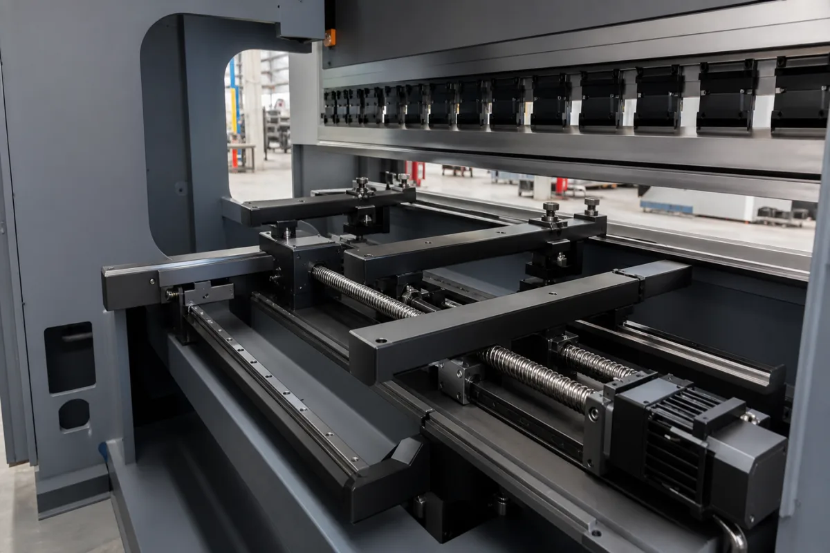
Back gauge system in use: how the blank is gauged against the fingers so each bend line lands where the drawing puts it
Gauging the blank against press brake back gauge fingers · Six ways to locate a bend line, stack-up from gauging off a bent flange, corner and tapered edges the standard finger cannot hold, printed inserts and front gauges
This page covers the back gauge from the gauging side: how the blank or a formed flange is placed against the stop fingers for each bend, which edges and features to gauge from, and what to do when a standard finger cannot hold the part. Ask three things first: which edge or feature each bend in the sequence will be gauged from, which corners and flanges the fingers must clear or capture, and whether a front gauge or custom finger insert is needed for the critical dimension.
Gauging practice on press brake back gauges: gauging methods, bend sequence for gauging, finger shapes, inserts and front gauges. Back gauge axes, per-axis accuracy, retract and collision zones, and new or retrofit back gauge hardware are covered on the Press brake back gauge page, the control of those axes on the CNC control system for press brakes page, and complete machines on the Hydraulic press brake page. Swing-beam folders, which do not gauge from a bent flange, are covered on the Metal plate folding machine page.
CNFX editorial research · Sources checked October 12, 2026 · 4 sources
Six ways to gauge a part, and why gauging off a previous bend stacks up error
Mark Watson of Cincinnati Inc., in The Fabricator, lists the ways to gauge a part on a press brake: the blank edge to the bend line, the simplest method and the ideal one in a good share of cases where tolerances are tight; a previously formed bend to the bend line, which works in a good share of cases but compounds errors that over multiple bends can stack up and force a part out of tolerance; a hole or feature to the bend line with a pin gauge, where that feature's position is critical; a tapered edge to a straight bend line, or a tapered bend line to a straight edge, where a 6-axis back gauge can carry a cornering finger that captures the edge; and an irregular edge to the bend line. [1]
Watson adds that bending order matters both to push error into the non-critical dimension and to leave a good gauging surface for every bend; a last bend that forces the part against the back gauge sliding upward at 30° rather than head-on is not an ideal gauging situation, and changing the sequence is the easiest fix where the design allows it. [1]
Editorial calculation: if each bend is gauged off the one before and each gauging carries ±0.1 mm, the fourth flange can be off by up to ±0.4 mm in the worst case, against ±0.1 mm when every bend is gauged from the cut blank edge. [1]
Give the supplier the part drawings with critical dimensions marked, the bend sequence you plan, the blank edges (cut, tabbed, deburred), any tapered, stepped or irregular edges, and the back gauge axes and finger types on the machine.
02
When the standard finger cannot hold the part: corners, side flanges, printed inserts and the front gauge
Watson likens a back gauge finger to a mitten: the part slides against the thumb for its front-to-back (X) position and against the finger section for its side (Z) position. That works for tapers until a flange is in the way, such as a bent flange protruding downward or a side flange, and a standard finger may not grip a 135° obtuse corner or a 55° acute corner, even on a 5- or 6-axis back gauge; a 3-D-printed insert shaped to the corner or slotted for the flange can solve it, since three points are enough to gauge any shape. For irregular edges he also describes laser-cutting a straight or tapered edge any 6-axis back gauge can handle and microtabbing the contour to break off after bending. [1]
Jim Ofria of Automec, also in The Fabricator, gives the case for a front gauge: on a 30 in. wide part with a 0.5 in. flange on each side, where the 30 in. between flanges is critical and the flange lengths are not, the first bend is made on the back gauge and the part is flipped so the bent edge sits against a front gauge set exactly 30 in. away, holding the critical dimension whatever the blank-size variation from cutting; he notes that operators avoid front gauges where they can because they are out in front and in the way. [2]
Finger hardware itself has long been designed around the moving blank: a 1981 Houdaille Industries patent describes gauging fingers that can be pulled out for replacement without falling out and are spring-loaded so they pivot upward in response to movement of the material. [3] G-Press lists a back gauge system among its press brake optional parts. [4]
03
Send the parts, the bend sequence and the gauging plan together
Paste it into your enquiry below or into an email to a maker, then replace every bracket.
Parts: [drawings; critical dimensions]
Sequence: [bend order; gauging edge per bend]
Edges: [cut; tabbed; tapered; irregular]
Fingers: [types; cornering; inserts]
Front gauge: [needed or not]
Machine: [back gauge axes; controller]
1 company lists this product among what they make. Company figures are quoted from each
company's own website; every card states where the relationship came from.
Explore company information and manufacturing capabilities, then discuss the scope of your project with a relevant supplier.
Share this page
Compiled and source-reviewed by the CNFX editorial team.
Each manufacturer above links to the page on that company's own website where the product is listed, with the date we checked it. How we source and review
· Page last updated 13 October 2026
Buyer questions
Why not gauge every bend off the previous flange?
The Fabricator notes that it compounds errors, which over multiple bends can stack up and force a part out of tolerance; gauging from the blank edge is the simplest method. [1]
What if the back gauge finger cannot hold a sharp corner?
The Fabricator describes 3-D-printed inserts shaped to 135° or 55° corners or slotted for side flanges, fitted to existing fingers. [1]
When is a front gauge better than the back gauge?
When the dimension between two flanges is critical, Automec's Jim Ofria describes flipping the part so the bent edge sits against a front gauge set to that dimension. [2]
Sources and what still needs a direct check
Sources checked 2026-10-12. Two Fabricator articles by press brake and back gauge makers' staff explain gauging; a 1981 patent describes finger design; G-Press lists its back gauge as an option.