Editorial Technical Reference

Conveyor Transfer System

This page explains how Conveyor Transfer System is classified within Fabricated Metal Product Manufacturing. Technical values and manufacturer relationships are research references; confirm the current specification and supplier evidence for each order.

Technical Definition & Core Assembly

A mechanical system that transfers aluminum profiles between different processing stations within an integrated fabrication line.
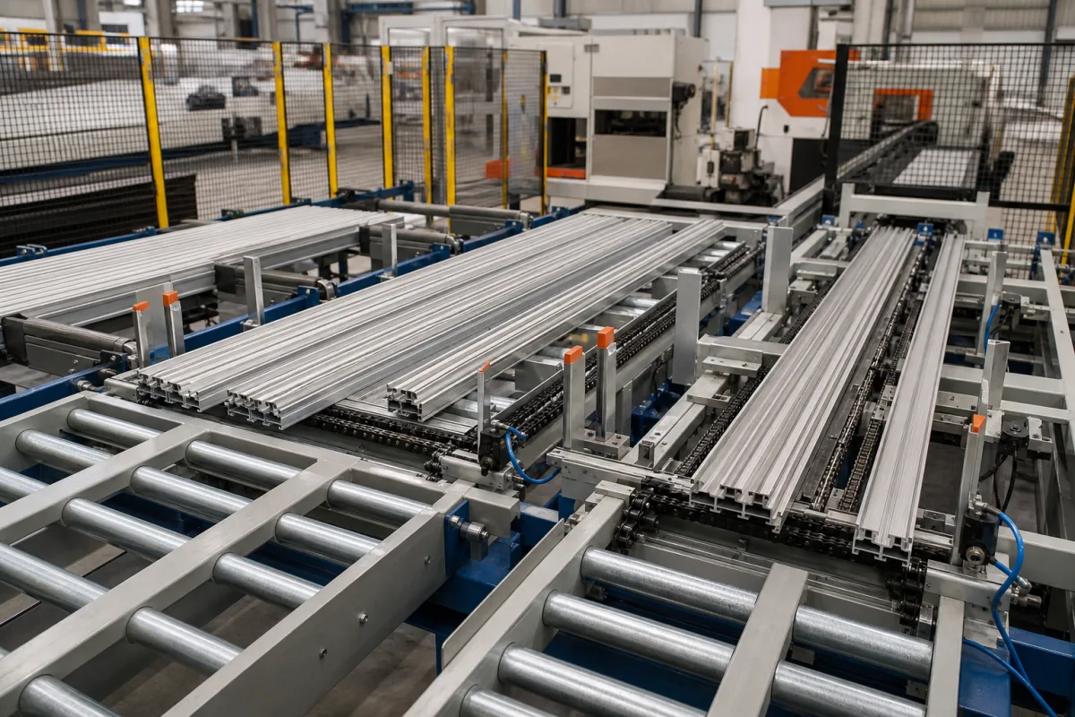
Representative product image. Confirm appearance and specifications with the manufacturer.

Product Specifications

Technical details and manufacturing context for Conveyor Transfer System

Definition
The Conveyor Transfer System is a component of the Aluminum Profile Integrated Fabrication System, designed to move aluminum profiles between processing stages such as cutting, drilling, milling, and assembly. It ensures continuous material flow, reduces manual handling, and maintains alignment accuracy. The system uses motor-driven belts, rollers, or chains, with sensors and controls to detect profile positions and synchronize with adjacent equipment. It handles profiles with widths from 20 to 300 mm, transfer speeds of 0.5 to 2.0 m/s, and load capacities up to 2000 kg. Positioning accuracy is ±0.5 mm, critical for downstream operations. Operating temperature ranges from -10°C to 60°C, and pneumatic pressure of 0.6 to 0.8 MPa is required. Power supply is 380 V AC ±10% (IEC 60038), with motor power from 1.5 to 5.5 kW and control voltage of 24 V DC ±10% (IEC 61131-2). Ingress protection is IP54 to IP65 (IEC 60529). Frame material is Q235B carbon steel (GB/T 700), rollers are 45# hard chrome plated steel (GB/T 699). Machine weight ranges from 800 to 1500 kg, and footprint is 3000×800×1200 mm (L×W×H). Materials include aluminum alloy, stainless steel, and industrial-grade polymers. These specifications are reference ranges; verify model-specific values with the manufacturer. The system is not a standalone machine but a transfer component; its performance depends on integration with the fabrication line. Regular maintenance includes checking belt tension, roller wear, and sensor alignment. Failure signs include misalignment, unusual noise, or jams. Confirm compatibility with your profile dimensions and processing requirements before selection.
Working Principle
The system uses motor-driven conveyor belts, rollers, or chains to transport profiles along predetermined paths. Sensors detect profile positions and send signals to a control unit, which synchronizes the transfer speed with adjacent processing modules. Pneumatic or mechanical mechanisms may assist in diverting or stopping profiles at specific stations. The control system ensures smooth transfers and prevents collisions. The system operates within specified speed and load ranges; exceeding them may cause misalignment. The working principle relies on precise coordination between mechanical components and control logic.
Common Materials
Aluminum alloy, Stainless steel, Industrial-grade polymers
Technical Parameters
ParameterTypical rangeNotes & selection driver
Transfer Speed0.5–2.0 m/sHigher speeds may cause profile misalignment
Load Capacity500–2000 kgMaximum total load on transfer system
Profile Width Range20–300 mmOutside range requires custom tooling
Positioning Accuracy±0.5 mmCritical for downstream processing
Operating Temperature-10–60 °CBelow -10°C seals may harden
Operating Pressure0.6–0.8 MPaBelow 0.6 MPa insufficient force
Power Supply380 ±10% V ACThree-phase, 50 HzIEC 60038
Motor Power1.5–5.5 kWDepends on load and speed
Control Voltage24 ±10% V DCFor PLC and sensorsIEC 61131-2
Ingress ProtectionIP54–IP65IP65 for dusty environmentsIEC 60529
Frame MaterialQ235BCarbon steel, paintedGB/T 700
Roller Material45#Steel, hard chrome platedGB/T 699
Machine Weight800–1500 kgVaries with length and options
Footprint (L×W×H)3000×800×1200 mmBase model, customizable

Ranges are indicative industry figures for RFQ preparation, not a supplier commitment. Confirm every value and standard with the legal manufacturer before ordering.

Components / BOM
  • Drive Motor
    Provides mechanical power to move conveyor elements
    Material: Steel housing with copper windings
  • Conveyor Belt/Roller Assembly
    Direct contact surface that transports aluminum profiles
    Material: Wear-resistant rubber or polyurethane
  • Transfer Mechanism
    Enables smooth transition between different conveyor sections
    Material: Precision-machined steel
  • Positioning Sensors
    Detects profile location and triggers transfer operations
    Material: Stainless steel with optical/inductive components
  • Control Unit
    Syncs transfer speed with the adjacent stations so profiles neither collide nor starve.
  • Diverter Mechanism Optional
    Pushes a profile off the main path or stops it at a station, on lines that need it.

Industrial Ecosystem & Supply Chain Structure

Complementary Systems
Downstream Applications
Specialized Tooling

Application Fit & Sizing Matrix

Operational Limits
pressure: N/A (mechanical system, not pressurized)
other spec: Max profile weight: 50 kg, Max profile length: 6 m, Transfer speed: 0.1-1.0 m/s
temperature: -10°C to +60°C
Media Compatibility
✓ Aluminum profiles (extruded) ✓ Aluminum alloy components ✓ Anodized aluminum parts
Unsuitable: Corrosive chemical environments (e.g., acid baths, salt spray chambers)
Sizing Data Required
  • Profile dimensions (length, width, height)
  • Production line throughput (units/hour)
  • Required transfer distance between stations

Reliability & Engineering Risk Analysis

Failure Mode & Root Cause
Belt misalignment and tracking failure
Cause: Improper installation, worn or damaged pulleys, uneven loading, or accumulation of material on rollers causing belt drift and edge damage.
Bearing seizure in rollers or pulleys
Cause: Inadequate lubrication, ingress of contaminants (dust, moisture), excessive belt tension leading to overload, or improper bearing alignment causing premature wear and failure.
Maintenance Indicators
  • Audible squealing, grinding, or scraping noises from rollers or bearings indicating lubrication failure or mechanical wear.
  • Visible belt wander, edge fraying, or material spillage along the conveyor path, signaling tracking issues or structural misalignment.
Engineering Tips
  • Implement a routine infrared thermography program to monitor roller and bearing temperatures, identifying overheating components before catastrophic failure.
  • Install and maintain automatic belt tracking systems with regular alignment checks, and use wear-resistant, crowned pulleys to reduce edge wear and extend belt life.

Indicative industry ranges for design and RFQ preparation. Confirm the exact figures and applicable standard with the manufacturer before specifying.

Compliance & Manufacturing Standards

Applicable Standards
ISO 5048:1989 - Continuous mechanical handling equipment - Belt conveyors with carrying idlers - Calculation of operating power and tensile forces ANSI/CEMA 402-2003 - Belt Conveyors DIN 22101:2011 - Continuous conveyors - Belt conveyors for loose bulk materials - Basics for calculation and dimensioning

Quoted from the published standard.

Manufacturing Precision
  • Belt alignment: +/- 3 mm over 10 m length
  • Roller concentricity: +/- 0.05 mm
Quality Inspection
  • Non-destructive testing (NDT) of welds using ultrasonic testing
  • Load testing with 125% of rated capacity for 4 hours

Manufacturers of Conveyor Transfer System

Manufacturer profiles associated with Conveyor Transfer System.

Sourcing Conveyor Transfer System from China?
Tell us your specification and target quantity — we will match it against manufacturer records and come back with the factories that fit.
Request manufacturers We manufacture this

Manufacturer listings support early research and capability understanding. They are not certification, ranking, or transaction guarantees.

Technical documentation
Request current drawings, revision history, and a signed specification sheet.
Manufacturing capability
Verify equipment lists, process limits, capacity, and representative production evidence.
Inspection readiness
Confirm test methods, calibrated equipment, sampling plans, and traceable reports.
Supplier transparency
Check the legal entity, factory address, ownership, certifications, and direct contacts.

CNFX does not score or rank suppliers. Buyers must verify all claims and documents with the legal manufacturer before ordering.

Supply Chain Compatible Machinery & Devices

Hydraulic Cylinder Piston Rod

A hydraulic cylinder piston rod is a precision-machined, load-bearing component that converts hydraulic pressure into linear mechanical force.

Explore Specs →
Industrial Tube Bending Machine

An industrial tube bending machine is a CNC-controlled device designed to precisely bend metal tubes and pipes to specific angles and radii.

Explore Specs →
Precision Linear Motion Guide Rail

Precision linear guide component for smooth, accurate motion in industrial machinery

Explore Specs →
Precision Aluminum Extrusion Profile

Precision aluminum extrusion profiles are semi-finished structural components produced by forcing heated aluminum alloy through a shaped die.

Explore Specs →

Frequently Asked Questions

What is the maximum load capacity of the Conveyor Transfer System?

The load capacity is specified as 500 to 2000 kg, depending on the configuration. This is a reference range; the actual capacity for a specific model must be confirmed with the manufacturer.

Can the system handle aluminum profiles of different widths?

Yes, the profile width range is 20 to 300 mm. Profiles outside this range may require custom tooling. Verify compatibility with your profile dimensions.

What is the positioning accuracy of the transfer system?

The positioning accuracy is ±0.5 mm, which is critical for downstream processing. This accuracy is maintained under specified operating conditions.

What are the power requirements for the system?

The system requires a three-phase 380 V AC ±10% power supply (IEC 60038) and a 24 V DC ±10% control voltage (IEC 61131-2). Motor power ranges from 1.5 to 5.5 kW. Confirm exact requirements with the manufacturer.

Data Basis

Editorial classification, named public sources where available, and source-reviewed manufacturer records.

Preliminary Technical Classification
This page supports structured research, RFQ preparation, and supplier evaluation. It does not replace buyer-led supplier qualification, standards review, or technical approval.
Buyer enquiry

Request manufacturing insight for Conveyor Transfer System

Ask for use case, specification boundaries, supplier type, and RFQ preparation information for this product.

Where it goes
Straight to the CNFX editorial desk, and to the manufacturer if this product is linked to a claimed profile. Nothing is broadcast to a supplier list.
Your details stay here
We do not sell or rent enquiry data, and we do not add you to a mailing list. Used only to answer this request.
No commission, no middleman
CNFX is a directory. We take no cut of any order and never negotiate on a supplier's behalf.
What we don't claim
A listing is not an endorsement. Qualify every supplier and verify every figure yourself before ordering.

Your business information is used only to process this request.

Thank you! Your message has been sent. We'll respond within 1–3 business days.
Sorry, we couldn't send your message. Please try again, or email us at contact@cnfx.com.

Need to Manufacture Conveyor Transfer System?

Compare manufacturer profiles with relevant product and process capability.

Previous Product
Welding Positioner
Last Product
Get QuotesChat