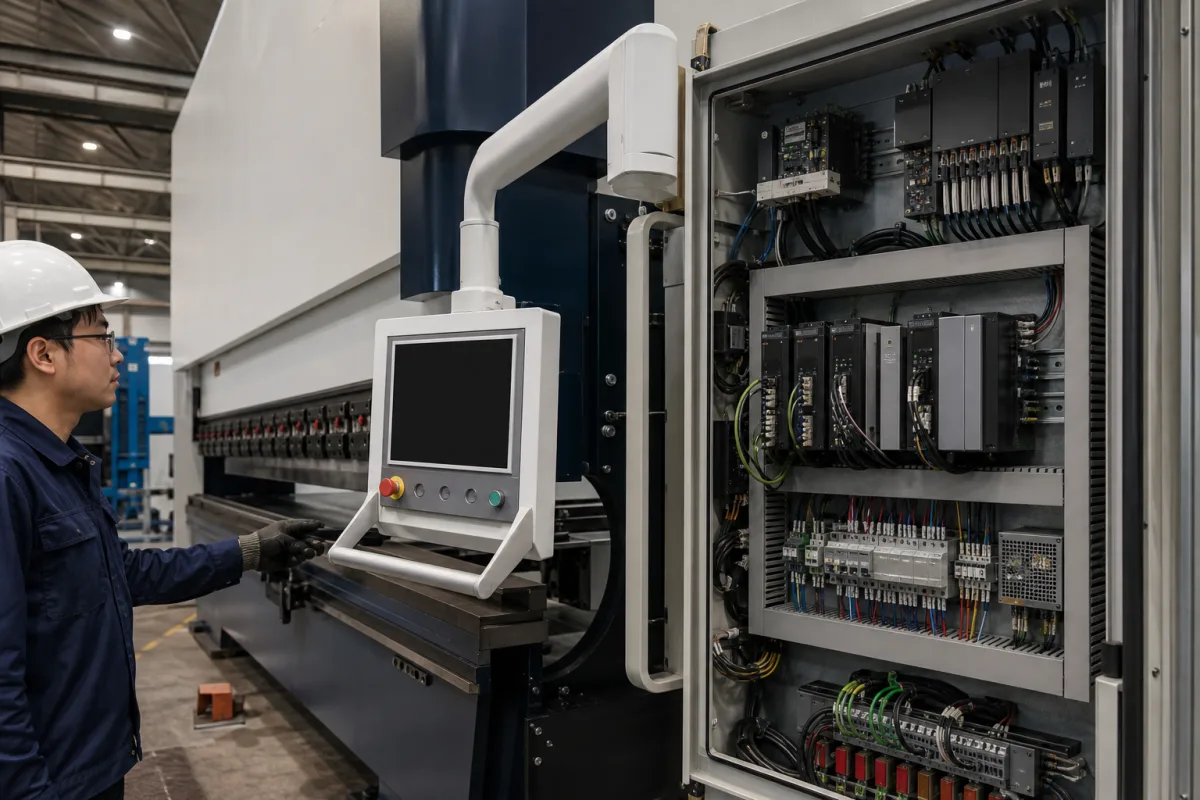
CNC control system for press brakes: synchronised Y1–Y2 beam, back gauge axes and valve outputs
Press brake CNC control systems · Synchronised Y1–Y2 beam axes, back gauge axes, valve and drive outputs, console and CNC rack
A CNC control system for a press brake is the operator console and controller electronics that synchronise the two hydraulic cylinders driving the upper beam (Y1 and Y2), position the back gauge axes, set pressure and crowning, and calculate bend depth, force and bend allowance from the programmed part. Buyers should check three things first: how many axes the control must run and which of them are synchronised hydraulic axes, whether its outputs match the machine's valves and drives, and what console, memory and environmental limits come with it.
Numerical control systems built for hydraulic and electro-hydraulic press brakes: touch-screen consoles, CNC racks and axis boards, valve and drive interfaces, and bending software. CNC controllers for milling machines, machining centres and lathes, with their look-ahead and path-accuracy settings, are covered on the CNC controller page. Complete press brakes are covered on the Hydraulic press brake page; shear controls, standalone servo drives and offline software sold alone are outside this page. The back gauge hardware itself, with its beam, drives, fingers and retrofit options, is on the Press brake back gauge page; here only the control side of those axes is treated.
CNFX editorial research · Sources checked October 12, 2026 · 4 sources
Count the axes: the synchronised Y1–Y2 beam plus back gauge axes
Delem's DA-53T is a compact touch control for synchronised press brakes that controls up to 4 axes as standard, described as Y1, Y2 plus 2 auxiliary axes; its standard machine functions are Y1-Y2, X, R-axis and crowning, and the second back gauge axis can be set as a Z axis. [1] Cybelec's CybTouch 12 PS is likewise designed for synchronised press brakes with 4 axes, with six ±10 VDC analog outputs assigned to Y1-Y2-X-R, pressure and crowning. [3]
At the upper end, Cybelec's ModEva 19T controls high-end synchronised press brakes with up to 18 axes, of which 2 are synchronised hydraulic axes. Its datasheet names the axes: Y1-Y2 for the beam; X, X1, X2, X5 and X6 as main back gauge axes; Z, Z2, Z5 and Z6 for left/right movement of the back gauge; R, R2, R5 and R6 for back gauge height; M1 and M2 for die movement; and, as software options, front gauge axes, sheet support axes and tandem operation of two or more coupled press brakes. [4]
The ModEva CNC rack sets the axis count by size and board type: the compact rack with NMX and NSX analog boards controls 2, 4 or 6 axes (Y1, Y2 and 2 or 4 electrical axes); the medium rack controls 4 to 12 axes; with the NCX CANopen axis board either rack reaches 18 axes (Y1, Y2 and 16 electrical axes). Each NMX or NSX board drives 2 analog axes with a ±10 VDC speed command and reads an incremental encoder; an NCX board controls up to 8 axes over a CAN bus. [4]
Editorial note: list the axes your press brake has or needs (for example Y1, Y2, X, R, Z1, Z2 and crowning) before comparing controls; a 4-axis control such as the DA-53T or CybTouch 12 PS covers Y1, Y2 and two back gauge axes, not a six-axis back gauge. [1][3]
Give the supplier the press brake type (hydraulic synchronised, tandem), beam valve type, list of axes and their drives, crowning type, safety system and safety PLC, required bending functions (automatic sequence, angle measurement, hemming), console mounting, and the languages needed.
02
Match the control outputs to the machine's valves and drives
Delem's DA-66T lists servo or 2-speed AC control, unipolar or frequency inverter control, direct pressure valve control, direct proportional valve control of Y1 and Y2, direct crowning control, multiple digital function outputs and tandem operation; it runs on a 24 V supply and links to Delem's Modusys modules over an HSB bus, with SafetyPLC, protractor and angle control interfacing. [2] The DA-53T integrates the valve amplifier for Y1, Y2 and pressure, and takes single-ended or differential 5 V or 12 V encoder inputs. [1]
Cybelec specifies its analog outputs as ±10 VDC, output impedance under 100 Ω, load at least 2 kΩ (max 15 mA). Where a valve needs current rather than voltage, it lists conversion modules fitted in the electrical cabinet: MSV-402 converts ±10 V to ±50 mA or ±300 mA for servo-valves, and MVP-100 converts 0–10 V to current for pressure and crowning valves; an interface card is offered for HOERBIGER proportional valves. [3][4]
Encoder requirements differ between the two Cybelec controls: CybTouch 12 PS accepts encoders with or without complementary signals and supplies 5 VDC at up to 250 mA per encoder, while the ModEva CNC requires 5 V DC line-driver encoders with complementary signals. [3][4]
Editorial calculation: the ModEva CNC power supply is listed as 24 VDC at up to 4 A, so the rack draws up to about 96 W; CybTouch 12 PS lists 30 W at 24 VDC. [4][3]
03
Compare control formats
The reviewed datasheets describe these formats, from a compact panel to a console with a separate CNC rack.
Format and example
What the source lists
Ask about
Compact 4-axis touch control (Delem DA-53T)
10.1" 1024 × 600 touch screen, 1 GB storage, tool library of 30 punches and 30 dies, IP54, 9 kg including housing; housing or panel version. [1]
Axes needed beyond Y1, Y2, X, R.
Compact 4-axis touch control (Cybelec CybTouch 12 PS)
Explore company information and manufacturing capabilities, then discuss the scope of your project with a relevant supplier.
Share this page
Compiled and source-reviewed by the CNFX editorial team.
Each manufacturer above links to the page on that company's own website where the product is listed, with the date we checked it. How we source and review
· Page last updated 13 October 2026
Buyer questions
How many axes does a press brake CNC control need?
At least the two synchronised beam axes Y1 and Y2 plus the back gauge axes; Delem's DA-53T and Cybelec's CybTouch 12 PS control 4 axes, and Cybelec's ModEva 19T up to 18. [1][3][4]
What signals does a press brake control send to the valves?
Cybelec lists ±10 VDC analog outputs for Y1, Y2, X, R, pressure and crowning, with modules converting voltage to current for servo, pressure and crowning valves. [3][4]
What does the control calculate for each bend?
Delem's DA-66T lists press force, bend allowance, crowning adjustment, developed length, bottoming and hemming force, and a learned angle correction database. [2]
Sources and what still needs a direct check
Sources checked 2026-10-12. Delem (Netherlands) and Cybelec (Switzerland) are press brake control makers publishing datasheets for their own controls.