Editorial Technical Reference

Automatic Tool-Changer

This page explains how Automatic Tool-Changer is classified within Machinery and Equipment Manufacturing. Technical values and manufacturer relationships are research references; confirm the current specification and supplier evidence for each order.

Technical Definition & Core Assembly

A mechanical device that automatically exchanges tools on a machine tool or robotic system without manual intervention.
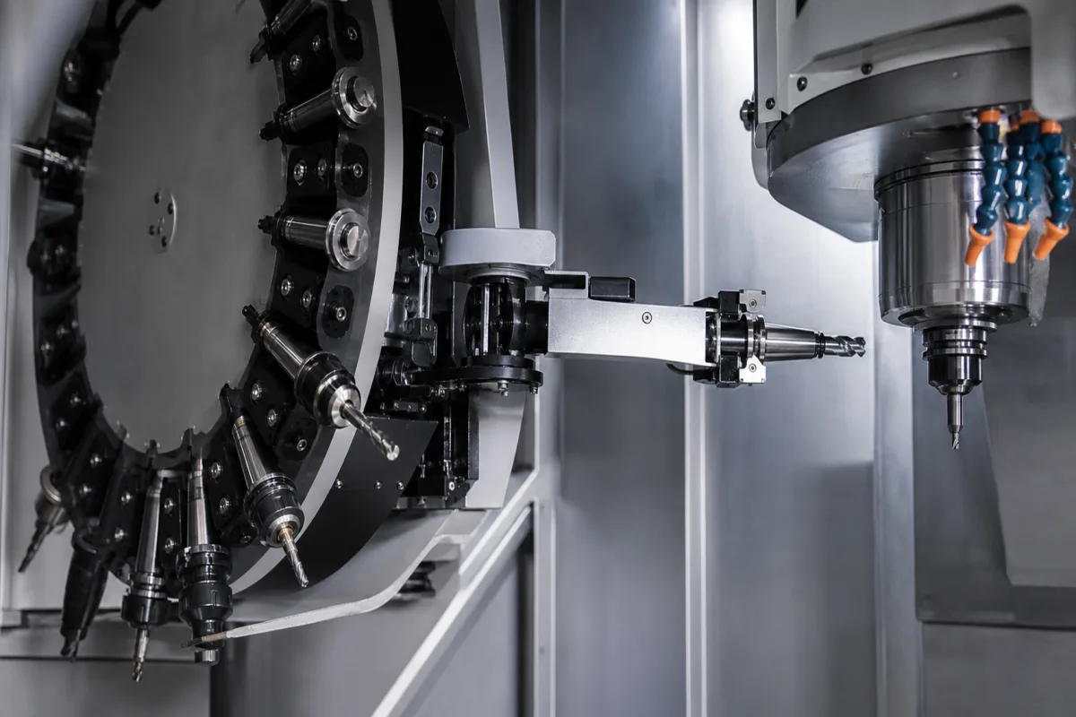
Automatic Tool-Changer in a manufacturing environment
Representative product image. Confirm appearance and specifications with the manufacturer.

Product Specifications

Technical details and manufacturing context for Automatic Tool-Changer

Definition
An Automatic Tool-Changer is a critical component within an Industrial System, typically integrated into CNC machine tools, machining centers, or robotic work cells. Its primary function is to store multiple tools and automatically swap the active tool in the machine spindle with a new tool from the magazine based on programmed instructions. This enables uninterrupted, multi-operation machining processes, significantly reducing setup times, increasing productivity, and enabling complex part production in a single setup. The device consists of a tool magazine (drum, chain, or carousel) that holds multiple tool holders, and a mechanical arm or similar mechanism that performs the exchange. The tool change sequence is initiated by the machine's CNC system, which commands the spindle to move to a fixed tool change position. The arm grips the current tool, retracts it, rotates or moves to align with the next required tool in the magazine, inserts the new tool into the spindle, and locks it in place. This sequence is driven by servo motors or pneumatic/hydraulic actuators. Tool identification is often managed via RFID chips, mechanical coding, or positional tracking. The device is designed to handle a range of tool sizes and weights, with typical specifications including a tool storage capacity of 16 to 60 tools, maximum tool diameter of 75 to 125 mm, maximum tool length of 250 to 400 mm, and maximum tool weight of 8 to 15 kg. Tool change time ranges from 1.5 to 8 seconds, and positioning repeatability is within ±0.02 to ±0.05 mm per ISO 230-2. Operating pressure is 0.6 to 1.0 MPa, supply voltage is 24 V DC ±10%, and power consumption is 0.5 to 2.0 kW. The device operates in ambient temperatures from -10 to 60 °C and has an ingress protection rating of IP54 to IP65 per IEC 60529. The magazine body is typically made of cast iron grade HT250 per GB/T 9439, and the complete unit weighs 350 to 800 kg. Materials used include high-strength steel alloy, precision bearings, and aluminum alloy for housings. These values are reference ranges; verify model-specific specifications with the manufacturer.
Working Principle
The Automatic Tool-Changer physically functions through a coordinated sequence. A tool magazine (drum, chain, or carousel) holds multiple tool holders. When a tool change is commanded, the machine spindle moves to a fixed tool change position. A mechanical arm (or similar mechanism) grips the current tool in the spindle, retracts it, rotates or moves to align with the next required tool in the magazine, inserts the new tool into the spindle, and locks it in place. This sequence is driven by servo motors or pneumatic/hydraulic actuators and controlled by the machine's CNC system. Tool identification is often managed via RFID chips, mechanical coding, or positional tracking.
Common Materials
High-Strength Steel Alloy, Precision Bearings, Aluminum Alloy (for housings)
Technical Parameters
ParameterTypical rangeNotes & selection driver
Tool Storage Capacity16–60 toolsNumber of tools that can be stored in the magazine.
Maximum Tool Diameter75–125 mmLargest tool diameter that can be accommodated.
Maximum Tool Length250–400 mmLongest tool that can be stored and changed.
Maximum Tool Weight8–15 kgHeaviest tool the changer can handle.
Tool Change Time1.5–8 sChip-to-chip time for a complete tool change.
Positioning Repeatability±0.02–±0.05 mmConsistency of tool positioning after repeated changes.ISO 230-2
Operating Pressure0.6–1.0 MPaPneumatic pressure for clamping and unclamping.
Supply Voltage24 ±10% V DCDC supply for control and sensors.
Power Consumption0.5–2.0 kWElectrical power drawn during operation.
Operating Temperature Range-10–60 °CAmbient temperature for reliable operation.
Ingress Protection RatingIP54–IP65Protection against dust and water ingress.IEC 60529
Magazine Body MaterialHT250Cast iron grade for rigidity and damping.GB/T 9439
Net Weight350–800 kgWeight of the complete tool changer unit.

Ranges are indicative industry figures for RFQ preparation, not a supplier commitment. Confirm every value and standard with the legal manufacturer before ordering.

Components / BOM
  • Tool Magazine
    Stores multiple tool holders in designated pockets, indexes to present the correct tool for exchange.
    Material: Steel or Aluminum structure
  • Tool Change Arm
    A dual-gripper mechanism that physically extracts the tool from the spindle and inserts the new tool from the magazine.
    Material: Forged steel or high-strength alloy
  • Tool Pot Part
    Individual pocket or holder within the magazine that secures a single tool holder.
    Material: Steel with wear-resistant lining
  • Drive Motor & Actuators
    Provides the mechanical power for arm movement, magazine rotation, and tool clamping/unclamping.
    Material: Electric servo motors, pneumatic cylinders, or hydraulic actuators

Application & selection

Application Fit & Sizing Matrix

Operational Limits
pressure: 0 to 10 bar
temperature: -10°C to 60°C
tool change time: 2 to 10 seconds
tool weight capacity: 1 to 50 kg
repeatability accuracy: ±0.005 mm
Media Compatibility
✓ CNC machining centers ✓ Industrial robots ✓ Additive manufacturing systems
Unsuitable: High-vibration environments without isolation
Sizing Data Required
  • Maximum tool weight and dimensions
  • Required tool change cycle time
  • Machine interface type and mounting constraints

Risk, maintenance & compliance

Reliability & Engineering Risk Analysis

Failure Mode & Root Cause
Misalignment-induced wear
Cause: Incorrect alignment during installation or thermal expansion causing tool-holder misalignment, leading to excessive friction and premature component failure.
Contamination-induced jamming
Cause: Ingress of metal chips, coolant, or debris into the tool-changer mechanism, causing binding, increased wear, or complete failure of moving parts.
Maintenance Indicators
  • Unusual grinding or scraping noises during tool changes
  • Visible metal shavings or debris accumulation around the tool-changer mechanism
Engineering Tips
  • Implement regular laser alignment checks and thermal compensation adjustments to maintain precise tool-holder positioning
  • Establish rigorous contamination control protocols including scheduled cleaning cycles and protective sealing maintenance

Indicative industry ranges for design and RFQ preparation. Confirm the exact figures and applicable standard with the manufacturer before specifying.

Compliance & Manufacturing Standards

Applicable Standards
ISO 9409-1:2004 (Interface for modular tooling systems) ANSI B5.50-1994 (Spindle noses and tool shanks for automatic tool changers) DIN 69871 (Interface for tool holders and tool shanks)

Quoted from the published standard.

Manufacturing Precision
  • Tool shank diameter: +/-0.005 mm
  • Spindle face runout: 0.002 mm TIR
Quality Inspection
  • Coordinate Measuring Machine (CMM) verification of interface geometry
  • Dynamic balancing test for rotating components
Technical documentation
Request current drawings, revision history, and a signed specification sheet.
Manufacturing capability
Verify equipment lists, process limits, capacity, and representative production evidence.
Inspection readiness
Confirm test methods, calibrated equipment, sampling plans, and traceable reports.
Supplier transparency
Check the legal entity, factory address, ownership, certifications, and direct contacts.

CNFX does not score or rank suppliers. Buyers must verify all claims and documents with the legal manufacturer before ordering.

Manufacturers of Automatic Tool-Changer

3 companies list this product among what they make. Company figures are quoted from each company's own website; every card states where the relationship came from.

Jinan Style Machinery Co., Ltd. (STYLECNC)
Jinan, Shandong, CN
Founded 2003
Listed on the company's own website · profile compiled by CNFX from public sources
View source page ↗ stylecnc.com · checked 2026-08-18
ERSM Machinery
Suzhou, Jiangsu, CN
Listed on the company's own website · profile compiled by CNFX from public sources
Listed there as: “Automatic Tool Changer”
View source page ↗ rsm-machinery.com · checked 2026-09-11
Linghang Robot Co.,Ltd
Henan, CN
Also makes: Tool Changer
Listed on the company's own website · profile compiled by CNFX from public sources
Listed there as: “LTC-0005A Automatic Tool Changer”
View source page ↗ robottoolchange.com · checked 2026-08-31

Manufacturer listings support early research and capability understanding. They are not certification, ranking, or transaction guarantees.

Buyer enquiry

Request manufacturing insight for Automatic Tool-Changer

Ask for use case, specification boundaries, supplier type, and RFQ preparation information for this product.

Where it goes
Straight to the CNFX editorial desk, and to the manufacturer if this product is linked to a claimed profile. Nothing is broadcast to a supplier list.
Your details stay here
We do not sell or rent enquiry data, and we do not add you to a mailing list. Used only to answer this request.
No commission, no middleman
CNFX is a directory. We take no cut of any order and never negotiate on a supplier's behalf.
What we don't claim
A listing is not an endorsement. Qualify every supplier and verify every figure yourself before ordering.

Your business information is used only to process this request.

Thank you! Your message has been sent. We'll respond within 1–3 business days.
Sorry, we couldn't send your message. Please try again, or email us at [email protected].

Frequently Asked Questions

What is the typical tool storage capacity of an automatic tool changer?

The tool storage capacity typically ranges from 16 to 60 tools, depending on the model and magazine type. This is a reference range; the exact capacity for a specific unit should be confirmed with the manufacturer.

How does the tool changer identify the correct tool?

Tool identification is managed via RFID chips, mechanical coding, or positional tracking. The CNC system uses this information to select the correct tool from the magazine based on the programmed sequence.

What is the chip-to-chip time for a tool change?

The chip-to-chip time, which is the total time for a complete tool change, typically ranges from 1.5 to 8 seconds. This includes the time from the end of one cut to the start of the next cut.

What standards are relevant for the automatic tool changer?

Relevant standards include ISO 230-2 for positioning repeatability, IEC 60529 for ingress protection, and GB/T 9439 for the magazine body material. These standards serve as verification references; compliance should be confirmed with the manufacturer.

Related equipment

Applied To / Applications

This component is essential for the following industrial systems and equipment:

Industry Taxonomies & Aliases

Commonly used trade names and technical identifiers for Automatic Tool-Changer.

Data Basis

Editorial classification, named public sources where available, and source-reviewed manufacturer records.

Preliminary Technical Classification
This page supports structured research, RFQ preparation, and supplier evaluation. It does not replace buyer-led supplier qualification, standards review, or technical approval.

Need to Manufacture Automatic Tool-Changer?

Compare manufacturer profiles with relevant product and process capability.

Previous Product
Automatic Tool Changer
Next Product
Automation Controller
Get QuotesChat