Editorial Technical Reference

Coolant Tank/Reservoir

This page explains how Coolant Tank/Reservoir is classified within Machinery and Equipment Manufacturing. Technical values and manufacturer relationships are research references; confirm the current specification and supplier evidence for each order.

Technical Definition & Core Assembly

The coolant tank or reservoir is a critical component of coolant systems that serves as a storage and supply vessel for coolant fluid.
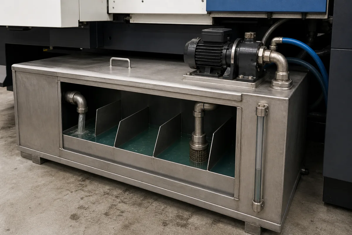
Coolant Tank/Reservoir in a manufacturing environment
Representative product image. Confirm appearance and specifications with the manufacturer.

Product Specifications

Technical details and manufacturing context for Coolant Tank/Reservoir

Definition
The coolant tank or reservoir is a critical component of coolant systems that serves as a storage and supply vessel for coolant fluid. It maintains proper coolant levels, allows for thermal expansion of the fluid, provides a visual indicator for coolant level monitoring, and often serves as a filling point for the system. In many systems, it also functions as a degassing chamber to remove air bubbles from the coolant. This component is used in machinery and equipment manufacturing, where it is integrated into cooling circuits to ensure consistent coolant availability and system stability. The tank is typically manufactured from materials such as polypropylene, high-density polyethylene, stainless steel, or aluminum, depending on the application requirements. Key parameters include capacity (10–500 L), operating pressure (0.1–0.6 MPa), operating temperature (-20 to 80 °C), wall thickness (2–6 mm), leakage rate (≤0.01 mL/min at rated pressure), surface finish (≤0.8 μm Ra, per ISO 1302), weight (5–200 kg), inlet/outlet connection (G1/4–G2, per ISO 228-1), pressure drop (≤0.05 MPa at rated flow), flow rate (5–100 L/min), and IP rating (IP54–IP65, per IEC 60529). Material grades such as 304/316L stainless steel are referenced per ASTM A240, with 316L recommended for corrosive coolants. These values are directory reference ranges and must be confirmed for the specific model and application. The tank operates by providing a sealed or vented reservoir that connects to the main coolant circulation system, maintaining a reserve of coolant that can be drawn into the system as needed. It compensates for thermal expansion and contraction, allows for visual inspection and replenishment, and in pressurized systems, maintains system pressure while accommodating volume changes. When selecting a coolant tank, consider system flow rate, heat load, and compatibility with the coolant. Verify model-specific parameters and standards with the legal manufacturer or supplier.
Working Principle
The coolant tank operates by providing a sealed or vented reservoir that connects to the main coolant circulation system. It maintains a reserve of coolant that can be drawn into the system as needed, compensates for thermal expansion and contraction of the coolant, and allows for easy visual inspection and replenishment of coolant levels. In pressurized systems, it maintains system pressure while accommodating volume changes. The tank may also serve as a degassing chamber to remove air bubbles, ensuring efficient heat transfer and preventing cavitation. Its design must accommodate the specified operating pressure and temperature ranges, with appropriate wall thickness and material selection to ensure structural integrity and leak-tightness.
Common Materials
Polypropylene, High-density polyethylene, Stainless steel, Aluminum
Technical Parameters
ParameterTypical rangeNotes & selection driver
Capacity10–500 LSelect based on system flow rate and heat load.
Operating Pressure0.1–0.6 MPaAbove 0.6 MPa may require reinforced design.
Operating Temperature-20–80 °CExceeding range may degrade seals and material.
Material304/316L316L for corrosive coolants.ASTM A240
Wall Thickness2–6 mmThicker for higher pressure or larger capacity.
Leakage Rate≤0.01 mL/minAt rated pressure.
Surface Finish≤0.8 μm RaSmoother for cleanliness and corrosion resistance.ISO 1302
Weight5–200 kgDepends on capacity and material.
Inlet/Outlet ConnectionG1/4–G2 inchThread size per system piping.ISO 228-1
Pressure Drop≤0.05 MPaAt rated flow rate.
Flow Rate5–100 L/minMatch to pump capacity.
IP RatingIP54–IP65Higher for dusty or wet environments.IEC 60529

Ranges are indicative industry figures for RFQ preparation, not a supplier commitment. Confirm every value and standard with the legal manufacturer before ordering.

Components / BOM
  • Reservoir Body
    The reservoir itself: holds the working fluid and lets air and contaminants separate out.
  • Filler Cap Part
    Seals the tank opening, maintains pressure, and allows for coolant addition
    Material: Plastic or metal with rubber seal
  • Sight Glass/Level Indicator
    Provides visual indication of coolant level within the tank
    Material: Transparent plastic or glass
  • Mounting Brackets Part
    Secures the tank to the equipment frame or structure
    Material: Steel or aluminum
  • Pressure Relief Valve
    Prevents over-pressurization by releasing excess pressure
    Material: Brass or stainless steel with spring mechanism
  • Inlet/Outlet Ports Part
    Connection points for coolant hoses to the main system
    Material: Molded plastic or metal fittings

Industry Taxonomies & Aliases

Commonly used trade names and technical identifiers for Coolant Tank/Reservoir.

Applied To / Applications

This component is essential for the following industrial systems and equipment:

Industrial Ecosystem & Supply Chain Structure

Complementary Systems
Downstream Applications
Specialized Tooling

Application Fit & Sizing Matrix

Operational Limits
pressure: 0 to 2 bar (gauge)
flow rate: 0 to 50 L/min
temperature: -20°C to +80°C
slurry concentration: 0 to 5% solids by weight
Media Compatibility
✓ Ethylene Glycol/Water Mix ✓ Propylene Glycol/Water Mix ✓ Deionized Water
Unsuitable: Hydrochloric Acid (HCl) solutions
Sizing Data Required
  • Required Coolant Volume (L)
  • Maximum System Flow Rate (L/min)
  • Available Installation Space (LxWxH in mm)

Reliability & Engineering Risk Analysis

Failure Mode & Root Cause
Corrosion
Cause: Chemical degradation of tank material due to coolant additives, pH imbalance, or galvanic reactions with dissimilar metals in the system.
Leakage at seams/welds
Cause: Thermal cycling stress, vibration-induced fatigue, or improper initial welding/joining leading to crack propagation.
Maintenance Indicators
  • Visible coolant seepage or puddles around the tank base or connections
  • Unusual gurgling or air-sucking sounds during pump operation indicating low fluid level or air ingress
Engineering Tips
  • Implement routine coolant analysis to monitor pH, concentration, and contaminant levels, adjusting as needed to prevent corrosive conditions.
  • Install vibration dampeners or flexible couplings on connected piping to reduce stress transfer to the tank, and conduct periodic weld inspections using non-destructive testing methods.

Indicative industry ranges for design and RFQ preparation. Confirm the exact figures and applicable standard with the manufacturer before specifying.

Compliance & Manufacturing Standards

Applicable Standards
ANSI/ASME B31.3 (Process Piping) DIN 4754 (Water heaters and storage tanks)

Quoted from the published standard.

Manufacturing Precision
  • Wall thickness: +/-0.5mm
  • Weld seam alignment: +/-1.0mm
Quality Inspection
  • Hydrostatic Pressure Test
  • Visual Inspection for Surface Defects

Manufacturers of Coolant Tank/Reservoir

1 company lists this product among what they make. Company figures are quoted from each company's own website; every card states where the relationship came from.

JTLD AUTOMOTIVE PARTS CO., LIMITED
Qingdao, Shandong, CN
Listed on the company's own website · profile compiled by CNFX from public sources
Listed there as: “Coolant tank”
View source page ↗ jtldautomotive.com · checked 2026-08-26

Manufacturer listings support early research and capability understanding. They are not certification, ranking, or transaction guarantees.

Share this page
Technical documentation
Request current drawings, revision history, and a signed specification sheet.
Manufacturing capability
Verify equipment lists, process limits, capacity, and representative production evidence.
Inspection readiness
Confirm test methods, calibrated equipment, sampling plans, and traceable reports.
Supplier transparency
Check the legal entity, factory address, ownership, certifications, and direct contacts.

CNFX does not score or rank suppliers. Buyers must verify all claims and documents with the legal manufacturer before ordering.

Supply Chain Compatible Machinery & Devices

Hydraulic Press

Industrial machine using hydraulic pressure to compress, form, or assemble materials

Explore Specs →
Heavy-Duty CNC Plasma Cutting Machine

The Heavy-Duty CNC Plasma Cutting Machine is a standalone industrial device designed for cutting conductive metals such as steel, stainless steel, aluminum, and copper alloys.

Explore Specs →
Automated Powder Coating System

Integrated industrial system for applying dry powder coatings to metal substrates.

Explore Specs →
Centrifugal Pump Impeller

The centrifugal pump impeller is a critical rotating component that converts mechanical energy from the motor into kinetic energy in fluid systems.

Explore Specs →

Frequently Asked Questions

What materials are commonly used for coolant tanks?

Common materials include polypropylene, high-density polyethylene, stainless steel (304/316L), and aluminum. The choice depends on the coolant type, operating temperature, and pressure requirements. For corrosive coolants, 316L stainless steel is often specified.

How do I determine the required capacity of a coolant tank?

Capacity should be selected based on the system's flow rate and heat load. The directory lists a reference range of 10–500 liters. Confirm the exact capacity needed for your application with the system designer or manufacturer.

What is the significance of the IP rating for a coolant tank?

The IP rating indicates the degree of protection against dust and water ingress. For dusty or wet environments, a higher rating such as IP65 is recommended. The reference range is IP54–IP65, per IEC 60529. Verify the required rating for your installation conditions.

Can a coolant tank be used in pressurized systems?

Yes, but the tank must be designed to handle the operating pressure. The reference range is 0.1–0.6 MPa, and above 0.6 MPa a reinforced design may be necessary. Always verify the pressure rating with the manufacturer.

Data Basis

Editorial classification, named public sources where available, and source-reviewed manufacturer records.

Preliminary Technical Classification
This page supports structured research, RFQ preparation, and supplier evaluation. It does not replace buyer-led supplier qualification, standards review, or technical approval.
Buyer enquiry

Request manufacturing insight for Coolant Tank/Reservoir

Ask for use case, specification boundaries, supplier type, and RFQ preparation information for this product.

Where it goes
Straight to the CNFX editorial desk, and to the manufacturer if this product is linked to a claimed profile. Nothing is broadcast to a supplier list.
Your details stay here
We do not sell or rent enquiry data, and we do not add you to a mailing list. Used only to answer this request.
No commission, no middleman
CNFX is a directory. We take no cut of any order and never negotiate on a supplier's behalf.
What we don't claim
A listing is not an endorsement. Qualify every supplier and verify every figure yourself before ordering.

Your business information is used only to process this request.

Thank you! Your message has been sent. We'll respond within 1–3 business days.
Sorry, we couldn't send your message. Please try again, or email us at [email protected].

Need to Manufacture Coolant Tank/Reservoir?

Compare manufacturer profiles with relevant product and process capability.

Previous Product
Z-axis Ram/Spindle
Last Product
Get QuotesChat