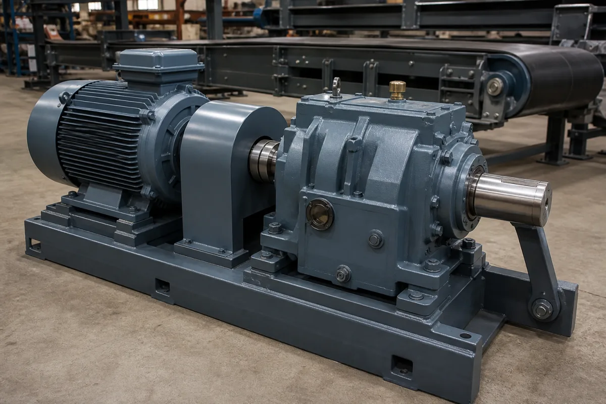
Explosion-protected motor and gearbox drive: an ATEX-marked gear unit and Ex motor for material handling in Zone 1, 2, 21 or 22, rated by category, temperature class and maximum surface temperature
Motor and gearbox for conveyors and machines in flammable gas or combustible dust · ATEX category and zone, the gear unit's own Ex h marking, surface temperature checks at commissioning, dust and oil maintenance
A gear motor driving a screw conveyor in a flour mill, a bucket elevator in a grain terminal or an agitator in a solvent plant has to be explosion-protected as a whole. The electric motor carries its own Ex certificate, but since the EU's ATEX directive covers non-electrical equipment too, the gear unit is a separately marked piece of equipment with its own category, temperature class or maximum surface temperature, and its own checks. What a buyer specifies is therefore the zone, the dust or gas group, the temperature limit and the ambient range — and then who measures the gear unit's surface temperature at commissioning and how dust and oil are kept in check afterwards.
Motor-and-gearbox drives (geared motors and gear units with a separate Ex motor) built for explosive gas or dust atmospheres: ATEX and IECEx categories and zones, the Ex h marking of the gear unit, temperature class and maximum surface temperature, commissioning temperature measurement, and the dust, oil and inspection intervals that keep the rating valid. Gear motors chosen by ratio, service factor and gearing type, are covered on the Gear motor drive assembly page; conveyor drive packages with fluid couplings and backstops on the Conveyor drive unit page; thermal ratings of industrial reducers on the Gear Reducer page; roller-chain drives on the Power transmission by roller chain and sprockets page; explosion-protected operator stations on the Touchscreen HMI page.
CNFX editorial research · Sources checked October 13, 2026 · 3 sources
Two name plates, one rating: how the gear unit's Ex h marking and the motor's marking combine for Zone 1, 2, 21 or 22
NORD has supplied gear units designed to the EU explosion-protection directives since 2003, for Zones 1, 2, 21 and 22. Its gear units are assessed to the non-electrical standards DIN EN ISO 80079-36 and 80079-37 (2016 editions), while its Ex motors follow EN 60079-0, -7 and -31; category 2 motors carry a type test certificate, and category 3 motors and the gear units a declaration of conformity. [2]
Example markings in NORD's manual are II 2G Ex h IIC T4 Gb and II 3D Ex h IIIC T125°C Dc. On a geared motor the motor has its own ATEX plate, and the lower explosion protection of the two markings applies to the whole unit; a motor run from a frequency inverter needs ATEX approval for that duty. The unit may be used in gas (Zone 1 or 2) or dust (Zone 21 or 22) atmospheres but not in a hybrid mixture of both, which voids the gear unit's approval, and NORD's paint system is electrostatically tested for 2G Group IIC and 2D Group IIIC. [1] NORD's overview adds that it does not offer Ex gear units under IECEx, so an IECEx motor would be combined with an EU-certified gear unit. [2]
The NORD manual applies the ignition protection types of ISO 80079-37: constructional safety c (strength and thermal calculations, an overhaul interval, lubricant checks and a thermal check at commissioning), liquid immersion k (the gears run in an approved lubricant at a stated fill level) and control of ignition sources b (temperature monitoring of oil cooling systems). [1]
In the United States, OSHA's hazardous-location rule requires equipment to be marked with its class, group and operating temperature or range based on a 40 °C ambient, with the marking not above the ignition temperature of the gas or vapour; equipment for ambients above 40 °C carries both the maximum ambient and the operating temperature at it, and heat-producing equipment that stays at or below 100 °C need not carry a temperature marking. Zone-system equipment is marked in the form "Class I, Zone 0, AEx ia IIC T6", and equipment relying on the listed protection techniques may not be suitable below −20 °C unless approved for it. [3]
Field on a NORD Ex gear unit plate (B 2000)
What it states
Group
II (not for mines)
Category
2G or 3G for gas, 2D or 3D for dust
Type of protection
Ex h for non-electrical equipment, or an ignition protection type such as c
Explosion group
IIC or IIB for gas; IIIC or IIIB for dust
Temperature
Temperature class T1–T3 or T4 for gas, or a maximum surface temperature for dust, e.g. 125 °C
EPL
Gb, Db, Gc or Dc
X
Special documentation must be observed
State the zone (1, 2, 21 or 22), gas or dust group, required temperature class or maximum surface temperature, ambient range, whether the motor runs on an inverter, and ask for the declaration or certificate of both the gear unit and the motor.
02
The commissioning check: four hours at full load, a housing below 121 °C, and 15 °C of margin under the 135 °C limit
NORD's temperature class and surface-temperature figures assume normal installation, and the manual warns that small changes to the installation can have a significant effect on gear unit temperature. Gear units marked T4, or with a maximum surface temperature of 135 °C or less, carry a sticker printed 121 °C whose centre dot turns black if the surface has run too hot; a unit with a blackened dot is taken out of service. [1]
At commissioning, units marked T4 or below 200 °C are measured under maximum load (units marked T1–T3 or 200 °C are exempt). The gear unit runs at maximum speed and load for about 4 hours; then the housing surface temperature Tgm is measured near the sticker and the air temperature Tum close by, with an instrument covering 0–130 °C to at least ± 4 °C. The drive is stopped and the maker consulted unless the air temperature is within the plate range, Tgm is below 121 °C, the sticker is still white, and Tgm + Tu − Tum stays 15 °C below the limit — under 135 − 15 = 120 °C for a T4 gas unit, or under Tmax − 15 °C for a dust unit, where Tu is the top of the plate's ambient range. [1]
Editorial calculation, with example values only: a T4 unit with a plate ambient limit Tu of 40 °C, measured at Tgm = 95 °C in Tum = 25 °C air, gives 95 + 40 − 25 = 110 °C, which passes the 120 °C test; the same reading in 15 °C air gives 120 °C and fails. In direct sunlight NORD requires the ambient or cooling-air temperature to stay at least 10 K below Tu — with the example Tu of 40 °C, no more than 30 °C. [1]
Other operating limits in NORD B 2000
Value
Atmosphere for commissioning conditions
80–110 kPa ambient pressure, about 21 % oxygen [1]
Trips at 120 °C and stops the drive; gap to the conveyor wall ≤ 8 mm [1]
Oil cooling coil
Coolant inlet ≤ 40 °C (10 °C recommended), pressure ≤ 8 bar, required flow 10 l/min [1]
Agree who runs the four-hour full-load measurement, record Tgm, Tum and the plate Tu, and keep the record with the Ex documentation; specify a temperature sensor where the sticker cannot be seen.
03
Keeping the rating in service: dust over 5 mm, oil every 10,000 hours, overhaul by the plate interval
NORD's maintenance table ties explosion protection to routine work: dust and dirt raise surface temperature, poor lubrication raises temperature and can make sparks, and an unearthed housing can build up static. [1]
For category 2D units, dust deposits on the housing are removed when they are more than 5 mm thick, including inside covers and on the output shaft and shrink disc. The housing must be earthed, cleaned only with a damp cloth to avoid static, and not repainted with a paint that can charge; structural modifications void the approval, and repairs are made by NORD or a person authorised under explosion-protection regulations. Oil change intervals shorten above 80 °C oil temperature, in high humidity or aggressive surroundings. [1]
Couplings, pulleys, pumps, sensors and the motor attached to the gear unit must themselves be suitable for the zone; NORD notes that the couplings in its IEC and NEMA adapters carry no separate ATEX marking. [1]
Interval (NORD B 2000, Table 10)
Work
Weekly or every 100 operating hours
Look for leaks, unusual noise or vibration; check the temperature sticker on units with a cooling cover
Every 2,500 h, at least every six months
Oil level; rubber buffer, hoses, radial shaft seals and temperature sticker; remove dust (category 2D only)
Every 10,000 h, at least every 2 years (oil up to 80 °C)
Change the oil (interval doubled for synthetic oil); check the cooling coil; replace radial shaft seals
Every 20,000 h, at least every 4 years
Re-lubricate gear unit bearings, replace hoses, check the resistance thermometer (II2GD)
Plate interval MI, or at least every 10 years
General overhaul (categories 2G and 2D)
Build the dust-cleaning trigger, oil and seal intervals and the overhaul date from the name plate into the plant's maintenance plan, and list every attachment on the drive with its own Ex marking.
04
Drive details to send
Paste it into your enquiry below or into an email to a maker, then replace every bracket.
Location: [Zone 1, 2, 21 or 22; gas or dust group]
Temperature: [class or maximum surface temperature; ambient range]
Duty: [output torque and speed; operating points; inverter or mains]
Gear unit: [type; mounting position; back stop; cooling]
Motor: [Ex type of protection; inverter approval]
Attachments: [couplings, pulleys, sensors and their Ex marking]
Documents: [declaration of conformity; type test certificate; special documentation X]
Explore company information and manufacturing capabilities, then discuss the scope of your project with a relevant supplier.
Share this page
Compiled and source-reviewed by the CNFX editorial team.
Each manufacturer above links to the page on that company's own website where the product is listed, with the date we checked it. How we source and review
· Page last updated 13 October 2026
Buyer questions
Does the gearbox need its own ATEX marking or only the motor?
Both. NORD's gear units carry their own Ex h marking to ISO 80079-36, the motor has its own plate, and the lower of the two protections applies to the geared motor. [1][2]
How is an ATEX gear unit's temperature checked at commissioning?
NORD runs a T4 unit for about 4 hours at full load, then requires the housing to be below 121 °C and Tgm + Tu − Tum to stay below 135 °C − 15 °C. [1]
When must dust be cleaned off a gear unit in Zone 21 or 22?
NORD's manual for category 2D units says to remove dust deposits on the housing when they are more than 5 mm thick. [1]
What ambient temperature is a US hazardous-location temperature marking based on?
OSHA 1910.307 bases the operating-temperature marking on a 40 °C ambient; equipment for higher ambients is marked with both the maximum ambient and its operating temperature there. [3]
Sources and what still needs a direct check
Sources checked 2026-10-13. Three sources from two publishers: NORD DRIVESYSTEMS' B 2000 operating and assembly instructions for explosion-protected gear units and its overview of explosion-protected drive approvals, and OSHA's hazardous (classified) locations rule, 29 CFR 1910.307.