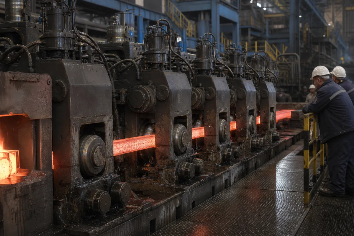
Withdrawal and straightening unit of a billet caster: pinch-roll withdrawal force and stepwise straightening strain
The driven roll stands at the end of a curved billet caster's arc: they pull the strand and the dummy bar out of the machine with hydraulically pressed rolls, and bend the strand back to straight in steps small enough not to crack the still-solidifying core
In a curved-mould billet caster the strand leaves the mould on an arc and has to come out of the machine straight and horizontal. The withdrawal and straightening unit does both jobs at the end of the arc: hydraulic cylinders press driven rolls onto the strand so that friction pulls it — and, at start-up, the dummy bar — at casting speed, and the roll positions bend the strand back to straight. Because the core of the billet may still be liquid or barely solid there, the unbending has to be spread over two or more rolls or a long enough length to keep strain below the level at which internal cracks open.
Withdrawal and straightening units (withdrawal-straightening machines, pinch-roll straighteners) of curved billet and bloom continuous casters: driven pinch-roll stands, hydraulic pressing cylinders, dummy-bar withdrawal and disconnection, and single-point, multi-point or continuous straightening of the strand. The complete caster, its sizing by section, speed and strand count, is covered on the Billet continuous caster page; strand guide segments up to the straightener on the Strand guide system page; mould oscillation on the Heavy-duty continuous casting mold oscillator page; secondary cooling sprays and chamber structure, cut-off torches and shears and ladle turret bearings on their own pages; straighteners for coil, bar and wire on the Straightener / leveler and Straightening roll pages.
CNFX editorial research · Sources checked October 12, 2026 · 5 sources
Pulling the strand: hydraulically pressed pinch rolls, friction of 0.2–0.3 and the dummy bar
Kobe Steel's 2010 patent on strand withdrawal sets out the force balance: each pair of drive rolls has a fixed-side roll and a pressure-side roll pressed by a hydraulic cylinder, and the retaining force on the strand or dummy bar is the friction produced by that pressing force. Its figures for an example withdrawing apparatus are: [1]
The patent's concern includes vertical facilities, where a strand slipping through the rolls can fall tens of metres; it reduces the pressure by about (n − 1)/n when n roll pairs share the load. [1] Editorial calculation: the dummy bar's friction coefficient of 0.1–0.15 is half or less of the hot strand's 0.2–0.3, so for the same pinch force the dummy bar is held with half or less of the friction force; check the start-up case as well as the cast strand when sizing cylinders.
An earlier Italian design shows the arrangement on a curved caster: two consecutive pinch-roll pairs, the first at the transition from the curved to the horizontal section drawing the casting at the set speed, the second held raised while the starting bar passes and then lowered to straighten the strand, its swing not altering the pinch pressure; each pair has at least one driven roll and its pinch pressure from a piston-cylinder assembly. [2]
0.2–0.3 on hot cast strand; 0.1–0.15 on the dummy bar (0.1 used in the example) [1]
Roll pairs and cylinder bore
Two pairs with 440 mm cylinders, or three pairs with about 310 mm cylinders [1]
Retaining force
About 55.8 t with two pairs, 55.4 t with three [1]
State strand section and weight, casting speed range, dummy bar type (rigid or chain) and weight, number of driven roll pairs, cylinder supply pressure and the friction coefficients the supplier has assumed.
02
Unbending without internal cracks: strain per straightening point, number of points and shell thickness
Nippon Steel's patent on low-height bow casters for slabs at least 200 mm thick puts conventional multi-point straightening strain at 0.1 to 0.25% per point and argues that strain above 0.2% becomes acceptable if the solidified shell is not more than 60 mm thick at the start and end of straightening, against an estimated 80–120 mm in conventional practice; it allows at least two and at most fifteen straightening points, with bulging strain kept to 0.4% or less. [3] In its first example (250 × 1,000 mm, 1.7 m/min) internal cracks fell to 0% against 30% in the comparison casting. [3]
For billets, a Concast patent on low-height arc casters with a rigid starting strand gives the corresponding rule as a rate: a maximum strain change on the strand surface of 0.002% per millimetre over a straightening section at least 1,000 mm long, for a 100 mm billet with a 2,500 mm arc radius. It notes that at radii of 3 m or less the elongation increases when straightening at the tangent point, and that too short a distance between the driving rolls and the straightening roll causes structural or surface defects. [4]
Editorial calculation: unbending a strand of thickness t from radius R to straight changes surface strain by about t/(2R); for the 100 mm billet at 2,500 mm radius that is 100 / 5,000 = 2%, and 0.002% per mm over 1,000 mm is the same 2%, so the patent's minimum length is the length needed to spread the whole unbending at its limiting rate. Spread over Nippon Steel's 0.1–0.25% per point, 2% would need roughly 8 to 20 points — more than its maximum of fifteen points at the lower figure.
Ask the supplier for the straightening layout (single-point, multi-point with the number of points, or continuous), the strain per point or per mm it is designed for, and the shell thickness expected at the straightener at maximum casting speed.
03
Caster radius sets the straightening duty: from 2.5 m low-head arcs to 9 m for high-carbon billets
The larger the arc radius, the less the strand has to be unbent. The Concast billet patent names 4 to 8 m as the radius a rigid starting strand otherwise needs, and develops its design for radii of 3 m or less. [4] At the other end, the six-strand, 1 Mt/y SMS Concast billet caster commissioned at JSPL's Raigarh works in 2012 has a 9 m casting radius for high-carbon, ball-bearing and free-machining steels, with withdrawal and straightening units designed for safe straightening of those steels as they leave the radius. [5]
Editorial calculation: using the same t/(2R) estimate, a 150 mm billet unbent from 9 m changes surface strain by about 0.83%, and from 6 m by about 1.25% — the larger radius roughly a third less, which matters for crack-sensitive high-carbon grades.
Editorial note: radius, section, casting speed and steel grade together decide how many straightening rolls the unit needs and where they sit; when replacing or upgrading a unit on an existing caster, give the supplier the machine radius and the metallurgical length as well as the section.
04
What to send for a withdrawal and straightening unit
Paste it into your enquiry below or into an email to a maker, then replace every bracket.
Caster: [radius; strands; sections; casting speed range; steel grades]
Withdrawal: [driven roll pairs; roll diameter; cylinder supply pressure; required retaining force]
Dummy bar: [rigid or chain; weight; disconnection method]
Straightening: [single-point, multi-point (number of points) or continuous; design strain]
Strand state: [shell thickness or liquid core at straightener; surface temperature]
Utilities: [roll and bearing cooling water; hydraulic system]
Explore company information and manufacturing capabilities, then discuss the scope of your project with a relevant supplier.
Share this page
Compiled and source-reviewed by the CNFX editorial team.
Each manufacturer above links to the page on that company's own website where the product is listed, with the date we checked it. How we source and review
· Page last updated 13 October 2026
Buyer questions
What does a withdrawal and straightening unit do?
Its hydraulically pressed, driven pinch rolls pull the strand and at start-up the dummy bar out of a curved caster, and its roll positions unbend the strand to horizontal. [1][2]
How much pinch pressure and friction are used?
Kobe Steel's patent example uses an 18 MPa source reduced to 9 MPa, 0.5–3 MPa retaining pressure in normal running, and friction of 0.2–0.3 on hot strand and 0.1–0.15 on the dummy bar. [1]
How much straightening strain is allowed?
Nippon Steel cites 0.1–0.25% per point for conventional multi-point straightening; a Concast billet patent limits strain change to 0.002% per mm over at least 1,000 mm. [3][4]
Why do some casters use a 9 m radius?
JSPL's SMS Concast billet caster uses 9 m for high-carbon, bearing and free-machining steels so they can be straightened safely as they leave the radius. [5]
Sources and what still needs a direct check
Sources checked 2026-10-12. Pinch pressure, friction and retaining force come from Kobe Steel's patent US 8,342,231; pinch-roll arrangement from P. Colombo's US 4,290,479; straightening strain and shell thickness from Nippon Steel's US 4,433,717; billet straightening rate and radii from Concast's EP 0 332 939; the 9 m radius caster from Steel Times International's report on JSPL.