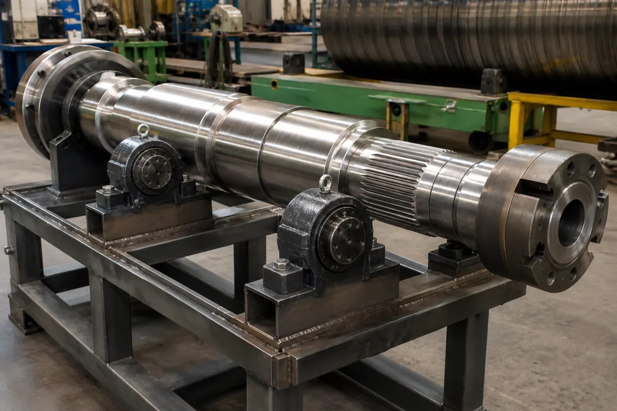
Stepped roll drive shaft: where it cracks and how the steps are cut
The shaft in the illustration is a heavy stepped forging for a roll drive: a series of diameters machined along its length, an external spline near one end, flanged ends, and two pillow-block bearings supporting it on a fabricated stand, with a large roll behind. On a shaft like this, fatigue cracks do not start in the middle of a plain diameter. They start where the diameter changes, at a spline or a groove, and the geometry of those few millimetres decides its life.
Covers heavy stepped drive shafts for rolls and similar driven machinery as components: fatigue crack initiation at shoulder transition arcs, fillet radius and stress concentration, surface residual stress and deep rolling, splines and relief grooves as stress raisers, and bearing-seat fillet, shoulder and grinding-undercut dimensions. Cardan universal joints and joint shafts are on Universal joint; automotive drive shafts and CV joints are outside this page.
CNFX editorial research · Sources checked October 13, 2026 · 3 sources
Pan and co-authors (Materials 18, 3747, 2025) analysed three EA1N steel axles from permanent-magnet direct-drive locomotives that failed early in wheel-seat bending tests.
One axle broke completely at 3 million cycles; magnetic particle inspection found cracks in the other two at 3.5 and 1.6 million cycles. Every fracture started at the transition arc between the wheel seat and the axle body, with ratchet marks and beach marks, and was identified as high-stress fatigue. The transition radius near the crack origin measured about 15.3 mm. Surface residual stress was tensile, about 100 MPa, and added to the operating stress it took the shoulder above the fatigue strength.
The authors cite an earlier drive shaft failure that started at a fillet of 1.58 mm where 2.5 mm was specified, and give an empirical stress concentration factor that falls as the fillet radius grows relative to the step. Their remedies: a larger fillet radius and better surface finish to move the critical stress zone off the arc, rolling the arc section to put it into residual compression, and optimised normalising and cooling for strength. The paper reports that newly manufactured axles did not fail prematurely in further testing. They also point to fretting at interference fits as a source of crack initiation.
Finding (Pan et al.)
Value
Cycles to fracture / crack detection
3.0 / 3.5 / 1.6 million
Crack origin
Wheel-seat to body transition arc
Transition radius at origin
≈15.3 mm
Surface residual stress
≈+100 MPa (tensile)
Cited drive shaft case: fillet as made vs specified
1.58 mm vs 2.5 mm
The cited fillet was 63% of the specified radius (Editorial calculation). Ask for the fillet radius tolerance and how it is checked, the surface finish at transitions, and whether transitions are deep-rolled.
02
Splines and relief grooves
Li and co-authors (Materials 19, 2164, 2026) built a low-cycle fatigue model for a drive shaft in an integrated transmission, loaded through involute splines.
Their shaft took input through a central involute spline and delivered output through involute splines at both ends. Relief grooves and splines, needed for assembly, make abrupt changes in cross-section and cause significant stress concentration, where high cyclic stresses initiate localised fatigue failure. Under relatively high cyclic stress, high-strength steels develop local plastic strain at such concentrations, so they used a strain-based (low-cycle) life approach with cumulative damage rather than a purely stress-based one.
On a roll drive shaft the same applies at the run-out of the spline and at any groove next to a shoulder: the spline root and groove bottom are where the section is smallest and the stress highest.
The application to roll drive shafts is an editorial reading. Ask how the spline run-out and groove radii are dimensioned, and whether fatigue was assessed for peak (start-up, jam) torques as well as running torque.
03
Bearing seats: small fillets, undercuts and shoulder height
A bearing seat pulls the other way. JTEKT's Koyo bearing guide limits the shaft fillet to clear the bearing's own corner chamfer.
Heavy axial loads need taller shoulders than the table, and the reduced "special" heights are not recommended for tapered roller, angular contact or spherical roller bearings. For ground shafts, Koyo gives grinding undercut dimensions (depth t, radius rg, width b) by chamfer size, for example 0.5 mm deep, 3 mm radius and 4.7 mm wide for a 3 mm chamfer.
So a bearing seat may allow only a 2.5 mm fillet where fatigue would favour a much larger one; an undercut gives the groove its own radius below the seat while the bearing still sits square on the shoulder (Editorial reading). The pillow blocks in the illustration sit on plain diameters for that reason.
Bearing chamfer r (min)
Shaft fillet ra (max)
Shoulder height h (min), general / special
1.5 mm
1.5 mm
4.25 / 4 mm
3 mm
2.5 mm
7 / 6.5 mm
5 mm
4 mm
11 / 10 mm
7.5 mm
6 mm
18 / 16 mm
Ask for the bearing chamfer and the seat fillet, shoulder height and undercut on the shaft drawing, and confirm the undercut radius is included in the fatigue check.
04
What to give a shaft supplier
Paste it into your enquiry below or into an email to a maker, then replace every bracket.
Send the shaft drawing with every diameter, fillet radius and tolerance, spline data and run-out, grooves and undercuts, bearing types and chamfers, material grade and heat treatment, and the torque spectrum including start-up and overload. Ask for fillet measurement method, surface finish at transitions, whether transitions are deep-rolled or shot-peened, residual stress or NDT checks, and the fatigue assessment at spline and shoulder sections.
Explore company information and manufacturing capabilities, then discuss the scope of your project with a relevant supplier.
Share this page
Compiled and source-reviewed by the CNFX editorial team.
Each manufacturer above links to the page on that company's own website where the product is listed, with the date we checked it. How we source and review
· Page last updated 13 October 2026
Buyer questions
Where do stepped shafts crack?
At the transition arc between diameters: in Pan et al.'s axles every crack started at the wheel-seat to body transition. [1]
How can a shoulder's fatigue life be raised?
Pan et al. propose a larger fillet radius, better surface finish and rolling the arc to replace a surface tensile residual stress of about 100 MPa with compression. [1]
Why are splines a fatigue risk?
Li et al. note that splines and relief grooves change the section abruptly and concentrate stress, where cyclic loading starts localised fatigue. [2]
How big can a fillet be at a bearing seat?
No bigger than the bearing chamfer allows: Koyo gives a maximum shaft fillet of 2.5 mm for a 3 mm chamfer, with a 7 mm minimum shoulder. [3]
Sources and what still needs a direct check
Sources checked 2026-10-13. Two peer-reviewed shaft fatigue studies and a bearing maker's mounting-dimension tables.