Editorial Technical Reference

Flow Control Valve/Meter

This page explains how Flow Control Valve/Meter is classified within Machinery and Equipment Manufacturing. Technical values and manufacturer relationships are research references; confirm the current specification and supplier evidence for each order.

Technical Definition & Core Assembly

A combined device that regulates and measures purge air flow in industrial systems
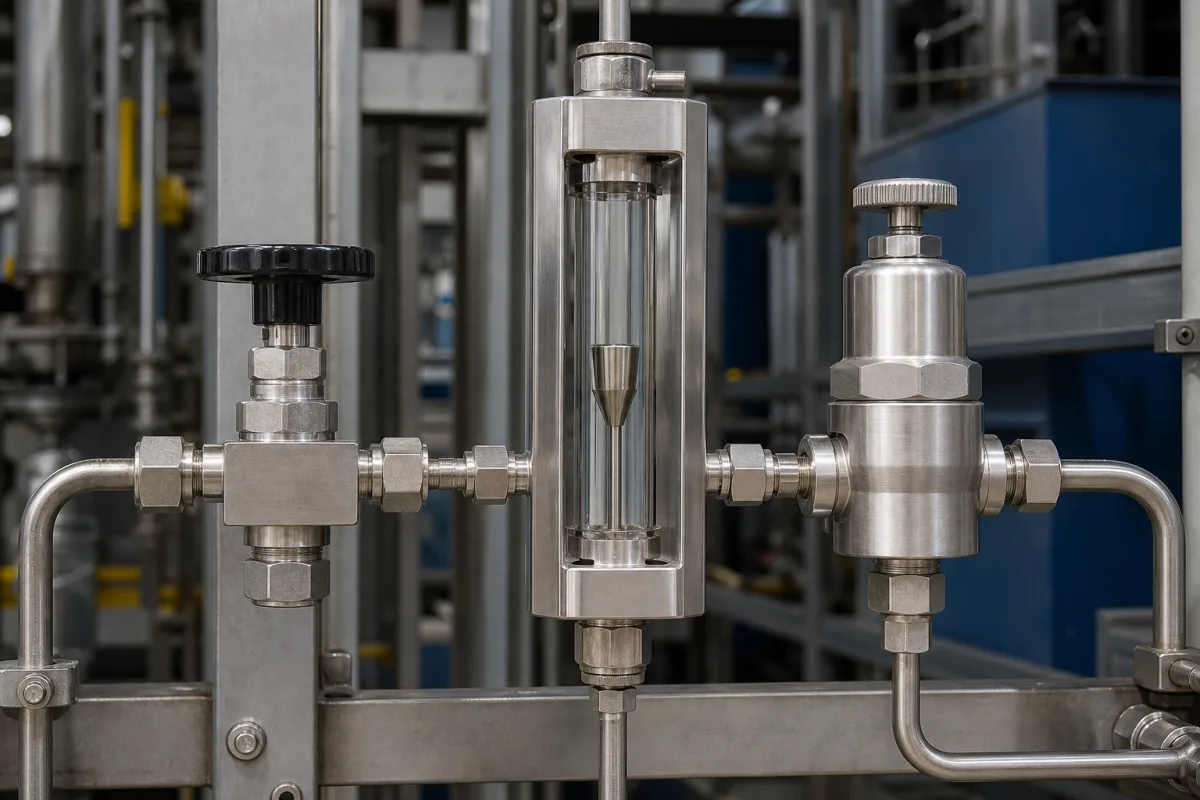
Representative product image. Confirm appearance and specifications with the manufacturer.

Product Specifications

Technical details and manufacturing context for Flow Control Valve/Meter

Definition
The Flow Control Valve/Meter is a component used in industrial purge air systems to simultaneously regulate and measure the flow of purge air. It is designed to ensure optimal air delivery for processes such as equipment cooling, contamination prevention, and pressure maintenance. The device integrates a control valve and a flow meter into a single unit, allowing for real-time adjustment of flow based on measurement feedback. The valve component can be actuated manually, pneumatically, or electrically to adjust the flow area, while the meter component typically uses differential pressure, thermal, or turbine principles to measure the actual flow rate. This integrated design simplifies installation and reduces space requirements compared to separate valve and meter arrangements. The device is available in nominal diameters from DN 15 to DN 100 (ISO 6708) and offers a flow coefficient (Cv) range of 2.5 to 160 (IEC 60534-2-1). Flow measurement accuracy is better than ±1.5% of reading (ISO 5167), and regulation accuracy maintains the setpoint within ±2% under varying inlet pressure (IEC 60534-4). Operating pressure ranges from 1.0 to 1.6 MPa, and operating temperature is -20 to 80°C (IEC 60534-4), with a high-temperature option up to 150°C. The device requires a 24 V DC supply voltage (IEC 61131-2) and uses an M12×1 electrical connection (IEC 61076-2-101). Ingress protection is IP65 to IP67 (IEC 60529). Body material is CF8M (equivalent to 316 stainless steel, ASTM A351), and seal material is FKM (fluorocarbon rubber, ASTM D1418). Weight ranges from 2.5 to 18 kg depending on size and actuator type. Materials on file include stainless steel, brass, PTFE seals, and aluminum alloy. All values are reference ranges and must be verified with the legal manufacturer or supplier for specific models and applications.
Working Principle
The valve component adjusts the flow area via manual, pneumatic, or electric actuation to regulate air volume. The meter component, typically using differential pressure, thermal, or turbine principles, measures the actual flow rate. The integrated design allows for real-time flow adjustment based on measurement feedback, ensuring precise control of purge air delivery. The device operates within specified pressure and temperature ranges, and its accuracy depends on proper installation and calibration. For selection, users must consider required flow range, operating pressure, temperature, and actuator type. Verification questions include checking the flow coefficient (Cv) against system requirements, confirming the nominal diameter matches piping, and ensuring the electrical connection and supply voltage are compatible. Maintenance signals include deviations in flow measurement accuracy or regulation accuracy, which may indicate sensor drift or valve wear. Failure boundaries include operation outside the specified pressure or temperature limits, which can damage seals or affect performance.
Common Materials
Stainless steel, Brass, PTFE seals, Aluminum alloy
Technical Parameters
ParameterTypical rangeNotes & selection driver
Nominal Diameter15–100 mmDN 15 to DN 100 for standard industrial pipingISO 6708
Flow Coefficient2.5–160 CvKv = 0.86 × Cv; select for required flow rangeIEC 60534-2-1
Flow Measurement Accuracy±1.5 % of readingBetter than ±1.5% for most purge air applicationsISO 5167
Regulation Accuracy±2.0 % of setpointMaintains setpoint within ±2% under varying inlet pressureIEC 60534-4
Operating Temperature-20–80 °CFor standard elastomer seals; high-temp option up to 150°CIEC 60534-4
Supply Voltage24 ±10% V DCFor electric actuator and sensor electronicsIEC 61131-2
Electrical ConnectionM12×1 connector4-pin for signal and powerIEC 61076-2-101
Ingress ProtectionIP65–IP67 IP ratingDust-tight and protected against water jetsIEC 60529
Body MaterialCF8M ASTM A351Equivalent to 316 stainless steel; corrosion resistantASTM A351
Seal MaterialFKM ASTM D1418Fluorocarbon rubber; compatible with most industrial gasesASTM D1418
Weight2.5–18 kgDepends on size and actuator type

Ranges are indicative industry figures for RFQ preparation, not a supplier commitment. Confirm every value and standard with the legal manufacturer before ordering.

Components / BOM
  • Valve Body
    Main housing containing flow passage and connection ports
    Material: Stainless steel or brass
  • Flow Meter Sensor
    Detects and measures air flow rate using various principles
    Material: Stainless steel with electronic components
  • Control Mechanism
    Adjusts valve opening to regulate flow (knob, actuator, etc.)
    Material: Aluminum alloy with plastic components
  • Seals and Gaskets Part
    Ensure leak-proof connections and internal sealing
    Material: PTFE, Viton, or EPDM rubber
  • Display/Output Module
    Shows flow readings and provides output signals
    Material: Polycarbonate with electronic circuitry

Applied To / Applications

This component is essential for the following industrial systems and equipment:

Industrial Ecosystem & Supply Chain Structure

Complementary Systems
Downstream Applications
Specialized Tooling

Application Fit & Sizing Matrix

Operational Limits
pressure: 0 to 10 bar (g)
flow rate: 0.1 to 100 Nm³/h
temperature: -20°C to +80°C
slurry concentration: Not applicable - designed for clean, dry purge air only
Media Compatibility
✓ Instrument air (clean, dry compressed air) ✓ Nitrogen (inert gas systems) ✓ Process air (non-corrosive, filtered)
Unsuitable: Corrosive gases (e.g., chlorine, ammonia) or particulate-laden streams
Sizing Data Required
  • Required purge flow rate (Nm³/h)
  • Upstream pressure (bar)
  • Required turndown ratio (max:min flow)

Reliability & Engineering Risk Analysis

Failure Mode & Root Cause
Cavitation
Cause: Pressure drop below vapor pressure causing bubble formation and implosion, damaging valve internals and trim surfaces.
Sticking/Binding
Cause: Accumulation of process media deposits, corrosion products, or foreign particles in valve stem, seat, or guiding surfaces.
Maintenance Indicators
  • Erratic or unstable flow measurement/control with hunting behavior
  • Unusual metallic grinding or scraping noises during operation
Engineering Tips
  • Implement regular valve stroking exercises during normal operation to prevent deposit buildup and verify full travel capability
  • Install upstream strainers/filters sized for process conditions and maintain differential pressure monitoring to detect clogging

Indicative industry ranges for design and RFQ preparation. Confirm the exact figures and applicable standard with the manufacturer before specifying.

Compliance & Manufacturing Standards

Applicable Standards
ISO 5208:2015 (Industrial valves - Pressure testing of valves) ANSI/FCI 70-2-2013 (Control Valve Seat Leakage) DIN EN 1349:2009 (Industrial valves - Metallic butterfly valves for general purposes)

Quoted from the published standard.

Manufacturing Precision
  • Bore diameter: +/-0.025mm
  • Surface flatness: 0.08mm per 100mm
Quality Inspection
  • Hydrostatic pressure test
  • Flow coefficient (Cv) verification test

Manufacturers of Flow Control Valve/Meter

Manufacturer profiles associated with Flow Control Valve/Meter.

Sourcing Flow Control Valve/Meter from China?
Tell us your specification and target quantity — we will match it against manufacturer records and come back with the factories that fit.
Request manufacturers We manufacture this

Manufacturer listings support early research and capability understanding. They are not certification, ranking, or transaction guarantees.

Technical documentation
Request current drawings, revision history, and a signed specification sheet.
Manufacturing capability
Verify equipment lists, process limits, capacity, and representative production evidence.
Inspection readiness
Confirm test methods, calibrated equipment, sampling plans, and traceable reports.
Supplier transparency
Check the legal entity, factory address, ownership, certifications, and direct contacts.

CNFX does not score or rank suppliers. Buyers must verify all claims and documents with the legal manufacturer before ordering.

Supply Chain Compatible Machinery & Devices

Hydraulic Press

Industrial machine using hydraulic pressure to compress, form, or assemble materials

Explore Specs →
Heavy-Duty CNC Plasma Cutting Machine

The Heavy-Duty CNC Plasma Cutting Machine is a standalone industrial device designed for cutting conductive metals such as steel, stainless steel, aluminum, and copper alloys.

Explore Specs →
Automated Powder Coating System

Integrated industrial system for applying dry powder coatings to metal substrates.

Explore Specs →
Centrifugal Pump Impeller

The centrifugal pump impeller is a critical rotating component that converts mechanical energy from the motor into kinetic energy in fluid systems.

Explore Specs →

Frequently Asked Questions

What is the purpose of a Flow Control Valve/Meter?

It regulates and measures the flow of purge air in industrial systems, ensuring optimal air delivery for cooling, contamination prevention, or pressure maintenance.

What are the available nominal diameters?

The nominal diameter ranges from DN 15 to DN 100, per ISO 6708. The specific size must be selected based on piping and flow requirements.

What is the flow measurement accuracy?

The flow measurement accuracy is better than ±1.5% of reading, per ISO 5167. This is a reference value and should be confirmed for the specific model.

What are the operating pressure and temperature limits?

Operating pressure is 1.0 to 1.6 MPa, and operating temperature is -20 to 80°C (IEC 60534-4), with a high-temperature option up to 150°C. Verify these limits with the manufacturer.

Data Basis

Editorial classification, named public sources where available, and source-reviewed manufacturer records.

Preliminary Technical Classification
This page supports structured research, RFQ preparation, and supplier evaluation. It does not replace buyer-led supplier qualification, standards review, or technical approval.
Buyer enquiry

Request manufacturing insight for Flow Control Valve/Meter

Ask for use case, specification boundaries, supplier type, and RFQ preparation information for this product.

Where it goes
Straight to the CNFX editorial desk, and to the manufacturer if this product is linked to a claimed profile. Nothing is broadcast to a supplier list.
Your details stay here
We do not sell or rent enquiry data, and we do not add you to a mailing list. Used only to answer this request.
No commission, no middleman
CNFX is a directory. We take no cut of any order and never negotiate on a supplier's behalf.
What we don't claim
A listing is not an endorsement. Qualify every supplier and verify every figure yourself before ordering.

Your business information is used only to process this request.

Thank you! Your message has been sent. We'll respond within 1–3 business days.
Sorry, we couldn't send your message. Please try again, or email us at contact@cnfx.com.

Need to Manufacture Flow Control Valve/Meter?

Compare manufacturer profiles with relevant product and process capability.

Previous Product
Flow Control Valve
Next Product
Flow Control Valves
Get QuotesChat