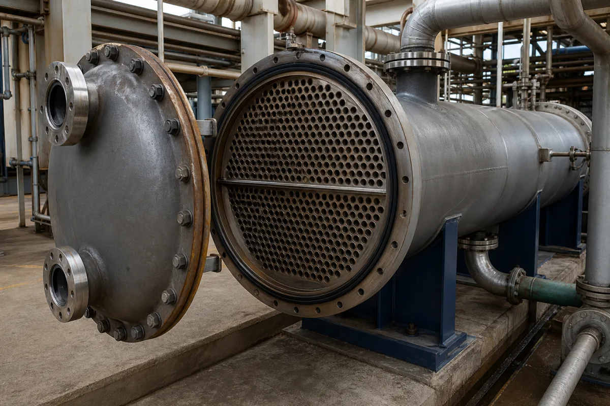
Water-cooled shell-and-tube refrigerant condenser for chillers and refrigeration plants
Refrigerant condensing on the shell side, cooling water in two- or four-pass tubes · AHRI 450 rating points and fouling, refrigerant-side and water-side design pressure, fresh-water copper or seawater CuNi 90-10 tubes
A water-cooled shell-and-tube refrigerant condenser takes hot refrigerant vapour from a compressor into its shell, condenses it on the outside of a tube bundle, and passes cooling-tower, city or sea water through the tubes in passes set by the front water box (two or four in the units reviewed). It is bought as a pressure vessel with two ratings, one for each side. Ask three things first: at which rating conditions and fouling allowance its heat rejection is quoted, the design pressure of the refrigerant side and the water side, and whether the tubes and tube sheets suit the water it will see.
Remote water-cooled shell-and-tube condensers for refrigerants (HFCs and similar) in chillers, refrigeration plants, process cooling and marine systems, with refrigerant on the shell side and water in the tubes, including seawater versions and their use as liquid receivers. Process and vapour-recovery condensers for chemical, solvent and fuel vapours are covered on the Condenser (process and vapour recovery) page, and hygienic tube-in-tube exchangers for food and dairy on the Tubular heat exchanger for food and dairy processing page. Air-cooled condensers, evaporative condensers, condensers built into packaged chillers as delivered and steam turbine surface condensers are outside this page. Coolers for CO2 running above its critical point, where the gas is cooled without condensing, are on the CO2 gas cooler for transcritical refrigeration and heat pump systems page.
CNFX editorial research · Sources checked October 12, 2026 · 3 sources
105 °F condensing with 85 to 95 °F water: what an AHRI 450 rating fixes
AHRI Standard 450-2007 covers testing and rating of the total heat rejection and water pressure drop of remote water-cooled refrigerant condensers, with tests to ASHRAE Standard 22. A published Standard Rating must give at least one of four rating conditions and be based on initially clean tubes, with water-side and refrigerant-side fouling factors taken as zero. [1]
Editorial calculation: in condition 2 the water warms 10 °F (5.6 K) and leaves 10 °F (5.6 K) below the condensing temperature; in condition 1 it warms 20 °F (11.1 K) with the same 10 °F leaving approach. A rating quoted at one condition cannot be compared directly with one quoted at another.
Fouled ratings are calculated, not tested: the standard takes the clean-tube overall coefficient Uc from test and adds the specified fouling factor to 1/Uc, with separate equations for fouling inside or outside the tubes. To comply, measured heat rejection must be at least 95% of the published rating and measured water pressure drop no more than 110% of it. [1]
AHRI 450 also asks makers to publish maximum and minimum recommended clean-water flow rates, design pressures for both sides, connection sizes, operating weight with refrigerant and water, and maximum refrigerant storage capacity, defined as 80% of the refrigerant-side volume at saturated liquid density at 90 °F (32.2 °C). [1]
Give the supplier the refrigerant, total heat rejection (compressor duty plus refrigeration capacity), saturated condensing temperature, entering and leaving water temperatures or water flow, the water-side fouling allowance you want included, and the allowed water pressure drop.
02
Refrigerant shell at 30 or 45 barg, water tubes at 10 or 16 barg: two pressure ratings on one vessel
Bitzer's CXP condensers for HFC refrigerants list a maximum allowable pressure (PS) of 30 barg on the shell (refrigerant) side in the standard version and 45 barg in the high-pressure version, against 10 and 16 barg on the tube (water) side, all for −10 to 120 °C, with PED (CE) approval. [2]
Editorial calculation: Bitzer's test pressures are 1.45 times PS on the shell side (43.6 ÷ 30, 65.4 ÷ 45) and 1.54 times on the tube side (15.4 ÷ 10, 24.6 ÷ 16). [2]
Carrier's 90C02 seawater condensers are built on the refrigerant side to ASME Section VIII Division 1 and stamped, dual-rated for 450 psi at 150 °F or 305 psi at 250 °F, with the water side designed for 150 psi at 150 °F; the shell side is tested at 1.1 times and the tube side at 1.3 times design pressure. [3] Editorial calculation: 450 psi ≈ 31.0 bar, 305 psi ≈ 21.0 bar and 150 psi ≈ 10.3 bar.
Editorial note: the refrigerant-side rating has to cover the highest condensing pressure the plant can reach, including warm water or a fouled bundle, for the refrigerant actually charged; the water-side rating has to cover pump shut-off head plus static head of the tower or sea-water circuit. AHRI 450 requires both design pressures and the refrigerant designation on the nameplate. [1]
Fresh water or seawater: copper or CuNi 90-10 tubes, water passes and acting as the receiver
In Bitzer's CXP the refrigerant condenses on the outside of the tubes and water flows inside. For normal water it uses copper tubes in a carbon steel tube sheet; the seawater CXPM version uses CuNi 90-10 tubes in a 316L stainless steel tube sheet with carbon steel anodes, both with polymeric tube supports and a carbon steel shell. A modular front water box gives two or four water passes. [2]
Bitzer lists CXP condensing capacities of 15 to 150 kW in shell diameters of 114, 141 and 168 mm and total lengths of 973 to 1,906 mm, using enhanced-surface tubes and quoted for temperature approaches as low as 1.5 K, for refrigerants including R404A, R407C, R134a and R410A. [2]
Carrier's 90C02 marine condensers cover 18 to 1,160 nominal kW (5 to 330 nominal tons) with 90/10 cupro-nickel enhanced tubes roller-expanded into grooved 90/10 cupro-nickel tube sheets, cast bronze heads for seawater, and steel shells to ASME specification. They include dual liquid refrigerant outlets to keep a liquid seal under pitch and roll and can hold the refrigerant charge when the system is off, removing the need for a separate receiver. [3]
Editorial note: if the condenser is also to serve as the receiver, check its storage capacity on the AHRI 450 basis (80% of refrigerant-side volume) against the full system charge. [1]
State the water source (cooling tower, city, river or sea water), its quality and velocity limits, the number of water passes, tube and tube-sheet materials, whether anodes are needed, and whether the condenser must hold the pump-down charge.
04
Send the refrigerant duty, water circuit and pressure ratings together
Paste it into your enquiry below or into an email to a maker, then replace every bracket.
Refrigerant: [designation; total heat rejection kW; condensing temperature; entering vapour temperature; subcooling]
Water: [source; entering/leaving °C or flow; fouling allowance; max pressure drop; passes]
Pressure: [refrigerant-side PS; water-side PS; code PED or ASME VIII-1]
Materials: [tubes copper or CuNi 90-10; tube sheet; heads; anodes]
Receiver duty: [pump-down charge kg]
Rating: [AHRI 450 condition or application rating]
Dimensions: [length; shell diameter; connections]
1 company lists this product among what they make. Company figures are quoted from each
company's own website; every card states where the relationship came from.
Shanghai Shenglin M&E Technology Co., Ltd.
Manufacturing site to be confirmed for the order
Shell And Tube Condenser page sits in its shell-and-tube range, which lists condensers alongside coolers, heaters, reboilers, evaporators and pressure vessels; no refrigerant ratings are given on the page.
Explore company information and manufacturing capabilities, then discuss the scope of your project with a relevant supplier.
Share this page
Compiled and source-reviewed by the CNFX editorial team.
Each manufacturer above links to the page on that company's own website where the product is listed, with the date we checked it. How we source and review
· Page last updated 13 October 2026
Buyer questions
What are the AHRI 450 standard rating conditions?
Four sets; for example condition 2 is 105 °F (40.6 °C) saturated condensing with water entering at 85 °F (29.4 °C) and leaving at 95 °F (35.0 °C), on clean tubes. [1]
Is fouling included in a standard rating?
No. AHRI 450 standard ratings assume zero fouling; fouled ratings are calculated by adding the fouling factor to 1/Uc. [1]
What design pressures do shell-and-tube refrigerant condensers carry?
Bitzer's CXP lists 30 or 45 barg on the refrigerant side and 10 or 16 barg on the water side; Carrier's 90C02 lists 450 psi at 150 °F on the refrigerant side and 150 psi on the water side. [2][3]
What tubes are used for seawater?
Bitzer's seawater CXPM uses CuNi 90-10 tubes in a 316L tube sheet; Carrier's 90C02 uses 90/10 cupro-nickel tubes and tube sheets with bronze heads. [2][3]
Sources and what still needs a direct check
Sources checked 2026-10-12. AHRI 450-2007 is the rating standard for this product; Bitzer and Carrier describe their own condenser ranges.