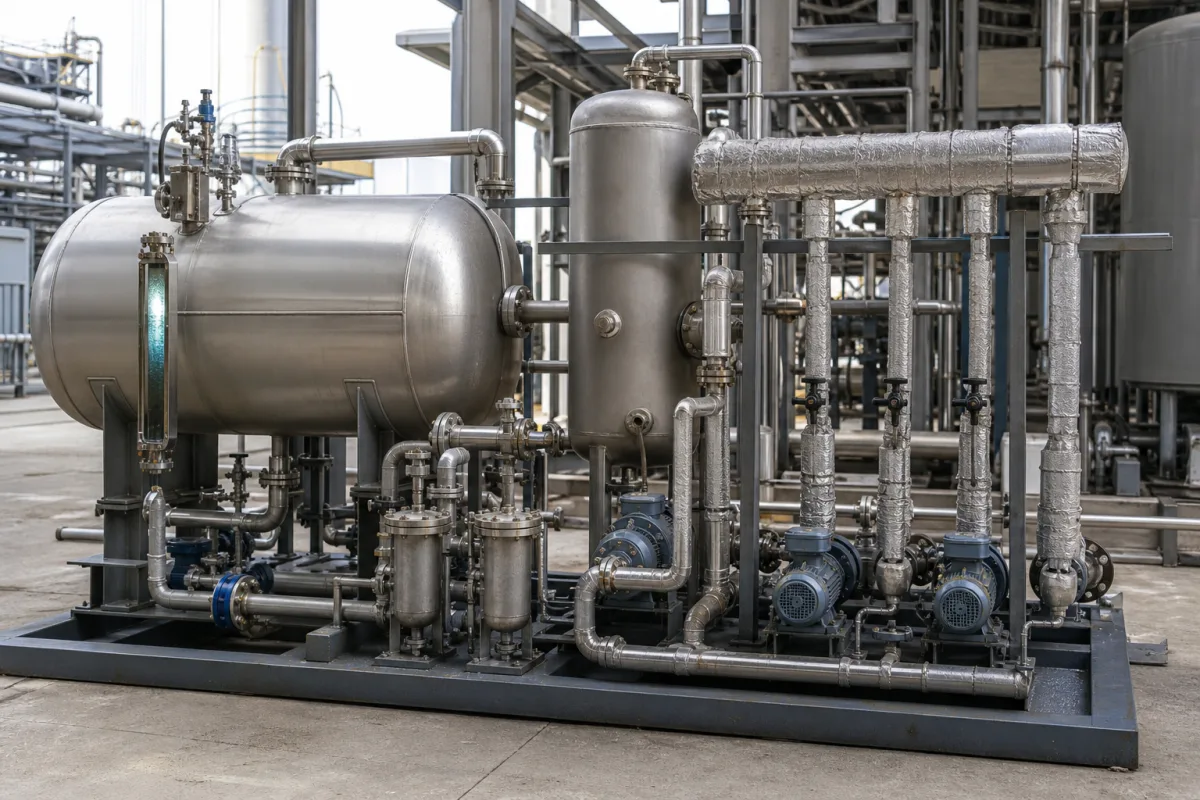
Condensate recovery system with flash steam vessel
Condensate recovery skids · Flash fraction by pressure, flash vessel velocities, back-pressure and relief, two-phase return piping
A condensate recovery system is the set of flash vessel, receiver, pumps, traps, valves and piping that takes condensate discharged from steam users, recovers flash steam for a low-pressure header and sends the remaining hot water back to the boiler house. Ask three things first: how much of your condensate will flash at the pressures involved, whether the flash vessel and its outlets are sized for that steam, and how the remaining condensate is returned without water hammer or back-pressure on the traps.
Packaged and site-built condensate recovery systems for steam plants: flash vessels, condensate receivers, return pumps, vessel traps, relief and back-pressure valves, and return piping. Individual steam traps are covered on the Steam trap page, and condensate pumps as separate machines on the Condensate pump page. Turbine surface condensers and process-condensate treatment (stripping or polishing) are outside this page.
CNFX editorial research · Sources checked October 12, 2026 · 3 sources
DOE's Steam Tip Sheet #12 tabulates the pounds of steam produced per pound of high-pressure condensate flashed. It states that flashing is attractive where returning high-pressure condensate to the boiler is not economically feasible. [1]
DOE's worked example flashes 5,000 lb/h of 150-psig condensate to 30 psig, producing 515 lb/h of low-pressure steam; with enthalpies of 1,171.9 Btu/lb for 30-psig steam and 38.0 Btu/lb for 70 °F make-up water, it values the saving at $40,924 a year at $8.00/MMBtu and continuous operation. [1]
TLV gives a flash ratio of roughly 10% by mass from 1 MPaG to 0.2 MPaG, but a steam-to-condensate volume ratio of about 62:1, so by volume the return line downstream of the traps carries about 62 parts flash steam to 1 part condensate; at lower line pressures it puts the specific volume of saturated steam at more than 1,000 times that of saturated condensate. [3]
Editorial calculation: 4,000 kg/h of condensate flashed from 200 psig to 5 psig gives 4,000 × 0.173 = 692 kg/h of steam, leaving 3,308 kg/h of liquid for return. The load is an assumed example. [1]
Give the supplier each condensate source with its flow (average and peak), pressure and temperature, the pressure and demand of the low-pressure steam user, the boiler house return point, available head and distance, and any risk of contamination in the condensate.
02
Size the flash vessel, outlets and protection
An NIH Office of Research Facilities technical bulletin (October 2023) states that flash tanks are stamped to ASME Section VIII, cites ASHRAE's preference for vertical tanks for better separation, and gives steam inlet velocities of 4,000–6,000 ft/min, with its design manual capping low-pressure steam at 6,000 ft/min. The internal diameter must slow steam in the tank to 10 ft/s to keep condensate out of the flash steam, and the flash steam outlet is sized for about 60 ft/s. [2]
The bulletin puts recoverable energy from flash steam at about 10%–40% of the condensate's energy content, depending on pressures. It calls for a trap on the tank's condensate outlet (disc thermodynamic traps for medium- and high-pressure service under its manual), swing check valves on inlets, inlet lines pitched toward the tank, a back-pressure regulator on the flash steam outlet set a few psi above design pressure, and safety relief valves vented above the roof line. It also advises that the low-pressure demand exceed the flash steam produced. [2]
Editorial calculation: 10 ft/s is about 3.0 m/s and 60 ft/s about 18.3 m/s; 6,000 ft/min equals 100 ft/s, or about 30.5 m/s. [2]
03
Return the remaining condensate without water hammer
TLV states that condensate lines collecting from traps must be sized for two-phase flow, not as water piping: calculate the flash steam first, use the specific volume of each phase to find the volume ratio, then size for allowable velocity and pressure drop. After a flash tank separates the phases, the liquid line can be designed to water-piping standards. [3]
TLV notes that live steam from leaking or bypassed traps, and corrosion or mud narrowing the pipe, raise velocity, pressure drop and back-pressure, and that long gravity returns of flashing condensate need design limits to avoid water hammer; the alternative is a local flash system with a pumped return in smaller pipe. [3] DOE adds that the condensate source should be close to the low-pressure header and that continuous flow suits heat recovery better than seasonal space heating. [1]
Explore company information and manufacturing capabilities, then discuss the scope of your project with a relevant supplier.
Share this page
Compiled and source-reviewed by the CNFX editorial team.
Each manufacturer above links to the page on that company's own website where the product is listed, with the date we checked it. How we source and review
· Page last updated 13 October 2026
Buyer questions
How much condensate flashes to steam?
DOE's Steam Tip Sheet #12 gives 10.3% from 150 to 30 psig and up to 17.3% from 200 to 5 psig. [1]
How big should a flash vessel be?
An NIH technical bulletin says the internal diameter must slow steam in the tank to 10 ft/s, with the flash steam outlet sized for about 60 ft/s. [2]
Why are condensate return lines larger than water lines?
TLV says return lines carry two-phase flow: about 10% flash by mass from 1 to 0.2 MPaG occupies about 62 times the volume of the liquid. [3]
Sources and what still needs a direct check
Sources checked 2026-10-12. DOE's tip sheet and the NIH Office of Research Facilities bulletin are US government guidance. TLV is a steam-equipment maker publishing engineering notes.