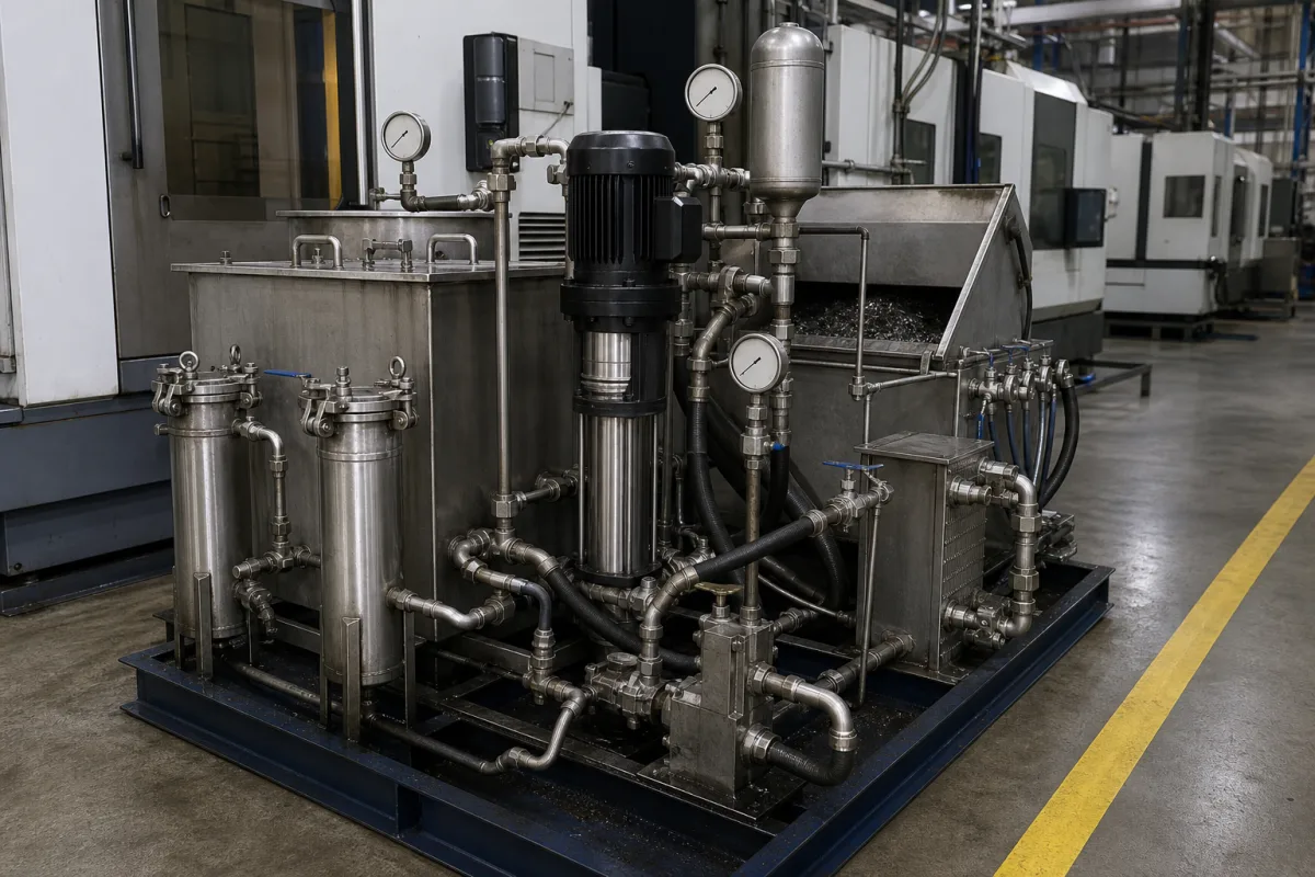
High-pressure coolant systems for CNC machining centres and lathes — through-spindle and through-tool coolant · pressure (400–2,500 psi), flow and reservoir, pump type (piston vs diaphragm), filtration to protect the pump, chillers, starvation and pulsation
A high-pressure coolant system is a pump, filter and reservoir unit that feeds coolant at high pressure through the machine spindle and tool, or through nozzles, directly to the cutting edge of CNC machining centres and lathes. Ask three things first: the pressure and flow your tools and operations need; the pump type and filtration that suit the material being cut; and how the unit will be sized and plumbed so the machine's coolant tank is not drained.
High-pressure coolant units for machine tools — through-spindle and through-tool coolant (TSC) systems with pumps, filtration, reservoirs, chillers and controls, fixed or variable pressure. Low-pressure flood coolant pumps, chip conveyors, central coolant filtration plants, minimum-quantity lubrication and coolant concentrate are outside this page except where compared.
CNFX editorial research · Sources checked October 12, 2026 · 4 sources
Cutting Tool Engineering (September 2017) reports ChipBlaster's view that 1,000 psi (69 bar) is truly high-pressure coolant, because at that pressure the coolant stream penetrates the steam barrier that forms at the cutting zone once temperature passes 100 °C, cooling tool, workpiece and chips. In one job drilling holes 10 diameters deep in 1018 steel with a 3.3 mm carbide drill, 300 psi (20.7 bar) coolant needed 53 drills, pecking five times per hole, to make 3,000 holes at 3,300 rpm and 10 ipm, while a 1,000-psi system produced the 3,000 holes with one drill at 10,000 rpm and 60 ipm without pecking. Another maker offers models up to 400, 1,000, 1,500 and 2,000 psi and custom systems to 2,500 psi (172 bar) and above, suggesting the 400-psi class for general cutting of mild steel and aluminium and the highest pressure for oil-cutting Swiss-type lathes; its 1,000-psi and higher units pump 8 gpm (30.3 L/min) with a 37-gallon (140.1 L) reservoir to avoid draining the machine tank and starving the system, since starvation causes pulsation that can break tools and scrap parts. [1]
Editorial calculation: in that drilling example the feed rose from 10 to 60 ipm — six times faster — and tool use fell from 53 drills to one for 3,000 holes, so drill cost per hole dropped by a factor of 53 before counting the time saved by not pecking. [1]
A peer-reviewed milling study in Heliyon (2023) gives laboratory numbers for a lower-pressure setup on Ti–6Al–4V. With biodegradable VG-68 cutting oil delivered at 80 bar and 2.0 L/min through a fixed external nozzle 20 mm from the impingement point, high-pressure cooling lowered average cutting temperature by 11.21–21.57%, resultant cutting force by 8.63–13.12% and mean surface roughness by 6.09–29.6% compared with dry milling, at 16–32 m/min cutting speed, 0.08–0.16 mm/tooth feed and 1.0 mm depth of cut. A rotary applicator feeding the same 2.0 L/min reduced them by 15.39–27.27%, 14.05–21.18% and 16.48–41.04%, and tool life rose by 6.8 min with the fixed nozzle and 9 min with the rotary applicator. Editorial calculation: 80 bar is about 1,160 psi, just above the 1,000 psi (69 bar) threshold cited above. [4]
Give the supplier the machines and spindle interface (through-spindle rating), operations and tools (drilling depth, tool diameters), coolant type (water-based or oil), required pressure and flow, fixed or variable pressure, reservoir size, filtration level, chiller need, pump type preference, power supply, controls and machine interface (M-codes), footprint, and quantity.
02
Choose the pump type and filtration
Wanner Engineering, quoted in the same article, says that because metal fragments "usually infiltrate the coolant, some type of filtration is typically included with packaged systems", and that "most pumps cannot handle particulates larger than 5µm" without a significant loss of pump life; its seal-less Hydra-Cell diaphragm pumps, with hydraulically balanced diaphragms and horizontal check valves, handle particulates up to 800 µm depending on model, keeping moving parts out of contact with the coolant. ChipBlaster recommends diaphragm pumps for abrasive, heavy-particulate work such as cast iron, cast aluminium, ceramics or glass, and piston-type positive-displacement pumps for general machining such as 1018 steel. [1] Jorgensen's FlexForce unit, for example, supplies 500–1,000 psi through-spindle coolant using a diaphragm pump and onboard reservoir, with single or duplex bag filters and an optional chiller. [2]
Editorial note: match filtration to the pump the supplier proposes — fine filtration for pumps that need clean coolant, coarser for diaphragm designs rated for particulates — and ask for the filter rating, change interval and duplex option so filters can be changed without stopping.
Wanner Engineering's own Hydra-Cell Machine Tool Coolant brochure (October 2019) lists ten seal-less diaphragm pump models with metallic liquid ends for this duty and says they tolerate solids up to 800 µm depending on model and can run dry without damage. Its selection guide includes the D10/D12 at 8.1 gpm (30.6 L/min) and 1,000 psi (69 bar), the D15 at 13.8 gpm (52.3 L/min) and 2,500 psi (172 bar), the H25 at 20.0 gpm (75.7 L/min) and 1,000 psi, and the D35 at 36.5 gpm (138 L/min) and 1,200 psi (83 bar), all rated to 121 °C. [3]
In Wanner's own energy comparison, delivering 7.66 gpm at 1,000 psi absorbed 8.3 kW with a screw pump against 4.2 kW with its D10. Editorial calculation: the hydraulic power in that duty is about 3.3 kW (29 L/min × 6.9 MPa ÷ 60), so the figures imply roughly 40% overall efficiency for the screw pump and 80% for the D10; these are the maker's comparison values, so ask any supplier for measured absorbed power at your duty point. [3]
03
Two Chinese pump makers with coolant-system pages
Aiken (China) Screw Pump and Dongguan Jiahe Pump each have a product page for high-pressure coolant systems; ask both for pressure and flow curves, pump type and filter rating.
When requesting quotations, ask each supplier for pressure and flow curves, pump type and particulate tolerance, filter rating, reservoir size, chiller capacity and machine-interface details.
04
Pump, filtration, reservoir, chiller and delivery
Pump type and filtration have to be chosen together, as the pump section explains; the reservoir row is what prevents starvation and pulsation.
Element
Role
Fix in the order
Pump
Piston or diaphragm; sets pressure and flow. [1][3]
2 companies list this product among what they make. Company figures are quoted from each
company's own website; every card states where the relationship came from.
Aiken(China)screw pump & system manufacturing co.,LTD
Manufacturing site to be confirmed for the order
Its website has a product page for high-pressure coolant systems.
Explore company information and manufacturing capabilities, then discuss the scope of your project with a relevant supplier.
Share this page
Compiled and source-reviewed by the CNFX editorial team.
Each manufacturer above links to the page on that company's own website where the product is listed, with the date we checked it. How we source and review
· Page last updated 13 October 2026
Buyer questions
What pressure counts as high-pressure coolant?
ChipBlaster, quoted by Cutting Tool Engineering, puts it at 1,000 psi (69 bar), enough to break the steam barrier at the cut. [1]
Why does a high-pressure unit need its own reservoir?
To avoid draining the machine tank and starving the system, which causes pulsation that can break tools. [1]
Diaphragm or piston pump?
Diaphragm pumps suit abrasive, heavy-particulate work such as cast iron or ceramics; piston pumps suit general machining. [1]
What particle size can a high-pressure coolant pump take?
Wanner says its seal-less Hydra-Cell diaphragm pumps tolerate solids up to 800 µm depending on model, at pressures up to 2,500 psi. [3]
How much does high-pressure coolant change cutting temperature in titanium milling?
In a 2023 Heliyon study milling Ti–6Al–4V with oil at 80 bar and 2.0 L/min, high-pressure cooling lowered average cutting temperature by 11.21–21.57% and cutting force by 8.63–13.12% compared with dry milling, and tool life rose by 6.8 min. [4]
Sources and what still needs a direct check
Sources checked 2026-10-12. The 2017 Cutting Tool Engineering article quotes makers of coolant systems and pumps (its PDF is hosted by Wanner Engineering), and a CTE product note describes Jorgensen's FlexForce unit; Wanner's 2019 brochure gives its own pump data; the Heliyon (2023) paper is a peer-reviewed milling study.