Editorial Technical Reference

Hydraulic Loading System

This page explains how Hydraulic Loading System is classified within Machinery and Equipment Manufacturing. Technical values and manufacturer relationships are research references; confirm the current specification and supplier evidence for each order.

Technical Definition & Core Assembly

A hydraulic system designed to apply controlled mechanical loads or forces within an industrial system
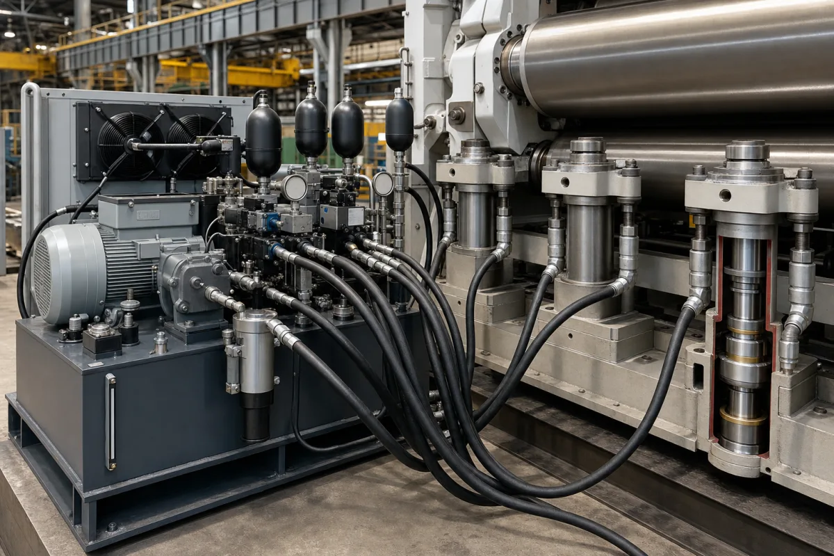
Representative product image. Confirm appearance and specifications with the manufacturer.

Product Specifications

Technical details and manufacturing context for Hydraulic Loading System

Definition
A hydraulic loading system is a critical component within industrial systems that utilizes hydraulic pressure to generate and apply precise mechanical forces for loading, pressing, or positioning operations. It serves as the force application mechanism in various industrial processes where controlled pressure and movement are required. The system typically comprises a hydraulic power unit, control valves, cylinders, and associated piping. It converts hydraulic energy into linear mechanical force, enabling tasks such as pressing, clamping, or testing. The system's performance is defined by parameters such as rated load capacity (50–500 kN), operating pressure (10–25 MPa), flow rate (20–100 L/min), positioning accuracy (±0.05 mm), response time (≤0.1 s), supply voltage (380 V AC ±10%), control signal (4–20 mA), operating temperature (-20 to 60 °C), ingress protection (IP54–IP65), cylinder material (45# steel per GB/T 699), seal material (NBR per ASTM D2000), and weight (150–800 kg). These values are reference ranges and must be verified for the specific model and application. The system is designed for integration into larger machinery, with interfaces for electrical and hydraulic connections. It is essential to confirm the exact specifications with the legal manufacturer or supplier before procurement. The system's reliability depends on proper maintenance, including regular inspection of seals and hydraulic fluid. Failure to operate within specified parameters may lead to reduced performance or system damage. Always consult the manufacturer's documentation for installation, operation, and maintenance guidelines.
Working Principle
The hydraulic loading system operates by converting hydraulic pressure from a pump into mechanical force through hydraulic cylinders. Hydraulic fluid is pressurized and directed to cylinders, where the pressure acts on piston surfaces to generate linear force. This force is then transmitted through mechanical linkages to apply controlled loads to workpieces or materials within the industrial system. The system uses a control signal (typically 4–20 mA) to regulate the flow and pressure, enabling precise load application. The response time is short (≤0.1 s) to achieve set loads quickly. The system's performance is influenced by operating pressure, flow rate, and temperature. Proper selection of hydraulic fluid and seals is critical for reliable operation. The system must be operated within the specified pressure and temperature ranges to avoid damage. Regular maintenance, including checking fluid levels and seal integrity, is necessary to ensure consistent performance.
Common Materials
High-strength steel, Hydraulic seals
Technical Parameters
ParameterTypical rangeNotes & selection driver
Rated Load Capacity50–500 kNMaximum force the system can apply
Operating Pressure10–25 MPaBelow 10 MPa insufficient forceISO 5208
Flow Rate20–100 L/minDetermines actuation speed
Positioning Accuracy±0.05 mmFor precise load application
Response Time≤0.1 sTime to reach set load
Supply Voltage380 ±10% V ACThree-phase powerIEC 60038
Control Signal4–20 mAAnalog control inputIEC 60381
Operating Temperature-20–60 °COutside range may affect performance
Ingress ProtectionIP54–IP65Dust and water resistanceIEC 60529
Cylinder Material45# steelHigh strength steelGB/T 699
Seal MaterialNBROil resistantASTM D2000
Weight150–800 kgDepends on capacity

Ranges are indicative industry figures for RFQ preparation, not a supplier commitment. Confirm every value and standard with the legal manufacturer before ordering.

Components / BOM
  • Hydraulic Cylinder
    Converts hydraulic pressure into linear mechanical force
    Material: High-strength steel with chrome plating
  • Hydraulic Pump
    Generates hydraulic pressure by moving fluid through the system
    Material: Cast iron or aluminum housing
  • Control Valve
    Regulates flow and direction of hydraulic fluid to control force application
    Material: Brass or stainless steel
  • Mechanical Linkage
    Carries the cylinder force to the point where the load is applied.

Industry Taxonomies & Aliases

Commonly used trade names and technical identifiers for Hydraulic Loading System.

Applied To / Applications

This component is essential for the following industrial systems and equipment:

Industrial Ecosystem & Supply Chain Structure

Complementary Systems
Downstream Applications
Specialized Tooling

Application Fit & Sizing Matrix

Operational Limits
pressure: Up to 300 bar (4350 psi)
flow rate: 5-100 L/min
temperature: -20°C to 80°C
slurry concentration: Up to 10% solids by weight
Media Compatibility
✓ Hydraulic oil (ISO VG 32-68) ✓ Water-glycol fluids ✓ Synthetic ester-based fluids
Unsuitable: Highly corrosive chemical environments (e.g., strong acids, chlorinated solvents)
Sizing Data Required
  • Maximum required force (kN)
  • Required stroke length (mm)
  • Operating cycle frequency (cycles/hour)

Reliability & Engineering Risk Analysis

Failure Mode & Root Cause
Seal degradation and leakage
Cause: Contamination from particulate matter in hydraulic fluid leading to abrasive wear, or chemical incompatibility with fluid causing swelling/hardening
Cylinder rod scoring and pitting
Cause: Inadequate filtration allowing abrasive particles to embed in seals, or improper rod surface finish creating stress concentrations
Maintenance Indicators
  • Audible knocking or hammering sounds during operation indicating cavitation or air entrainment
  • Visible external fluid leaks around cylinder seals or connections, especially with oil sheen on components
Engineering Tips
  • Implement proactive fluid analysis with particle counting and moisture monitoring to maintain ISO cleanliness codes
  • Establish proper rod wiper maintenance schedule and ensure correct rod surface finish (typically 0.2-0.4 μm Ra) to prevent seal damage

Indicative industry ranges for design and RFQ preparation. Confirm the exact figures and applicable standard with the manufacturer before specifying.

Compliance & Manufacturing Standards

Applicable Standards
ISO 4413: Hydraulic fluid power - General rules and safety requirements for systems and their components ANSI/B93.5M: Hydraulic fluid power - Cylinders - Bore and rod area ratios DIN 24342: Hydraulic cylinders - Piston rods with male thread

Quoted from the published standard.

Manufacturing Precision
  • Cylinder bore diameter: +/-0.025mm
  • Piston rod straightness: 0.05mm per meter length
Quality Inspection
  • Pressure testing: 1.5x maximum working pressure for 2 minutes
  • Dimensional verification with CMM (Coordinate Measuring Machine)

Manufacturers of Hydraulic Loading System

Manufacturer profiles associated with Hydraulic Loading System.

Sourcing Hydraulic Loading System from China?
Tell us your specification and target quantity — we will match it against manufacturer records and come back with the factories that fit.
Request manufacturers We manufacture this

Manufacturer listings support early research and capability understanding. They are not certification, ranking, or transaction guarantees.

Technical documentation
Request current drawings, revision history, and a signed specification sheet.
Manufacturing capability
Verify equipment lists, process limits, capacity, and representative production evidence.
Inspection readiness
Confirm test methods, calibrated equipment, sampling plans, and traceable reports.
Supplier transparency
Check the legal entity, factory address, ownership, certifications, and direct contacts.

CNFX does not score or rank suppliers. Buyers must verify all claims and documents with the legal manufacturer before ordering.

Supply Chain Commonly Integrated Components

Drive Motor

Electric motor that provides rotational power to drive the blending mechanism in pharmaceutical powder blending equipment

Explore Specs →
Air Handling Unit

A device that conditions and circulates air as part of a heating, ventilation, and air conditioning (HVAC) system

Explore Specs →
Cleaning-in-Place (CIP) System

An automated cleaning system that cleans processing equipment without disassembly, using spray nozzles, pumps, and cleaning solutions to remove residues and contaminants.

Explore Specs →
Vacuum System

A vacuum system that creates and maintains a controlled low-pressure environment for lyophilization by removing air and moisture from the chamber.

Explore Specs →

Frequently Asked Questions

What is the rated load capacity of the hydraulic loading system?

The rated load capacity is a reference range of 50–500 kN, as listed in the directory. The exact capacity for a specific model must be confirmed with the manufacturer or supplier, as it depends on the system configuration and application.

What operating pressure is required for the system?

The operating pressure range is 10–25 MPa, per the directory. Below 10 MPa, the system may not generate sufficient force. Compliance with listed standards must be verified with the manufacturer.

What is the positioning accuracy of the system?

The positioning accuracy is ±0.05 mm, which is a reference value for precise load application. Actual accuracy may vary depending on the installation and control system, so it should be verified for the specific model.

What are the electrical requirements for the system?

The system requires a three-phase power supply of 380 V AC ±10%, per IEC 60038. The control signal is 4–20 mA, per IEC 60381. These are reference values; the actual requirements should be confirmed with the manufacturer.

Data Basis

Editorial classification, named public sources where available, and source-reviewed manufacturer records.

Preliminary Technical Classification
This page supports structured research, RFQ preparation, and supplier evaluation. It does not replace buyer-led supplier qualification, standards review, or technical approval.
Buyer enquiry

Request manufacturing insight for Hydraulic Loading System

Ask for use case, specification boundaries, supplier type, and RFQ preparation information for this product.

Where it goes
Straight to the CNFX editorial desk, and to the manufacturer if this product is linked to a claimed profile. Nothing is broadcast to a supplier list.
Your details stay here
We do not sell or rent enquiry data, and we do not add you to a mailing list. Used only to answer this request.
No commission, no middleman
CNFX is a directory. We take no cut of any order and never negotiate on a supplier's behalf.
What we don't claim
A listing is not an endorsement. Qualify every supplier and verify every figure yourself before ordering.

Your business information is used only to process this request.

Thank you! Your message has been sent. We'll respond within 1–3 business days.
Sorry, we couldn't send your message. Please try again, or email us at contact@cnfx.com.

Need to Manufacture Hydraulic Loading System?

Compare manufacturer profiles with relevant product and process capability.

Previous Product
Hydraulic Excavator
Next Product
Hydraulic Mining Shovel
Get QuotesChat