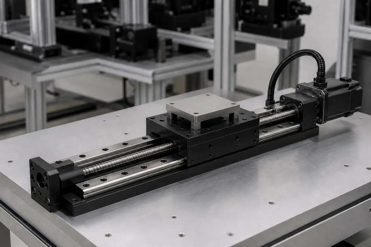
Single-axis motion · Ball screw accuracy grade against positioning accuracy, backlash, lead and speed against critical speed
A linear positioning stage is a single-axis module in which a carriage running on linear guides is driven along a base by a motor through a ball screw (or by belt, linear motor or a manual micrometer), to place a load at a commanded position. Ask three things first: what positioning accuracy and repeatability the task needs and which ball screw grade supports it, whether the motion reverses under load so that backlash matters, and what speed is needed for the travel so that the screw's lead and length stay below their speed limits.
Single-axis linear stages and modules driven by ball screws, including motorized and manual stages for automation, optics and inspection. Multi-axis gantries, linear motor stages, piezo nanopositioners as a product class, bare ball screws and linear guide rails are outside this page.
CNFX editorial research · Sources checked October 11, 2026 · 5 sources
Match the ball screw accuracy grade to positioning accuracy
THK explains that ball screw lead accuracy is controlled under JIS B 1192 (ISO 3408): grades C0 to C5 are defined by linearity and direction, C7 to C10 by travel distance error per 300 mm. Its permissible values for fluctuation per 300 mm of thread are 3.5 µm (C0), 5 µm (C1), 7 µm (C2), 8 µm (C3) and 18 µm (C5), and travel distance errors of ±50 µm (C7), ±100 µm (C8) and ±210 µm (C10) per 300 mm. [1]
For C3 and C5 the representative travel distance error grows with effective thread length: THK lists 13 µm (C3) and 25 µm (C5) for 315–400 mm of thread, and 21 µm and 40 µm for 800–1,000 mm. THK classes grades 0, 1, 3 and 5 for positioning and up to 10 for transport. [1] MISUMI states that grade selection is made by confirming that the required positioning accuracy is within the screw's actual mean travel error. [2]
MISUMI notes that backlash does not affect positioning accuracy when feeding in one direction only, but does when feed direction or load reverses, so backlash should be selected for the accuracy required. [2] Editorial note: stage accuracy also depends on guides, encoder or motor feedback, mounting and temperature; ask the supplier for measured positioning accuracy and bidirectional repeatability of the assembled stage, not only the screw grade.
Give the supplier the travel, payload and its offset from the carriage, orientation (horizontal, vertical, wall), required positioning accuracy and repeatability, speed and acceleration, duty cycle, whether motion reverses under load, motor and controller to be used, environment (dust, cleanroom, temperature), and acceptance test method.
02
Check lead and speed against critical speed and DmN
MISUMI explains that ball screw lead is chosen from the required feed speed, and that allowable rotational speed must respect both the screw's critical speed and the ball recirculation limit (DmN value); it defines allowable rotational speed as 80% of the critical speed, where rotation coincides with the shaft's natural frequency. Its worked example, a Ø15 mm screw with 5 mm lead, fixed–supported at a 790 mm span, gives an allowable 3,024 min⁻¹. [3]
Kuroda explains that the thinner and longer the screw, the lower its critical speed, that the mounting method (for example fixed–supported) and bearing arrangement can raise it, and also recommends running below 80% of critical speed, asking customers to contact it above about 2,000 min⁻¹. [4]
Editorial calculation: carriage speed = lead × rotational speed. MISUMI's 5 mm lead at 3,024 min⁻¹ gives 5 × 3,024 / 60 ≈ 252 mm/s. Fuyu's FSL120 module lists a maximum of 200 mm/s with G1610 or G2020 screws; if G1610 denotes a 10 mm lead (an assumption from the designation), 200 mm/s needs 200 × 60 / 10 = 1,200 min⁻¹. [3][5] Longer travel lowers the critical speed, so ask for the allowable speed at your full stroke.
03
Enclosed ball screw modules, stages from a ball screw maker, and optical linear stages
Listings range from enclosed ball screw modules for automation to positioning stages built around a maker's own ball screws and manual and motorized stages for optics; ask each for the screw grade, guide type, measured accuracy and repeatability, and allowable speed at your stroke.
04
Base, carriage, linear guides, ball screw and nut, screw supports, motor and feedback
The screw supports row ties to speed: Kuroda notes that the mounting method can raise critical speed, and MISUMI's 3,024 min⁻¹ example assumes a fixed–supported screw. [4][3]
Travel, load, positioning accuracy, repeatability, speed and screw grade for a linear stage order
Filled stage values come from one module, Fuyu's FSL120; repeatability carries no published figure, so ask for the bidirectional value measured on the assembled stage. [5]
3 companies list this product among what they make. Company figures are quoted from each
company's own website; every card states where the relationship came from.
FUYU Technology
Manufacturing site to be confirmed for the order
Lists enclosed ball screw linear modules such as the FSL120 with stated stroke, accuracy, speed and load.
Explore company information and manufacturing capabilities, then discuss the scope of your project with a relevant supplier.
Share this page
Compiled and source-reviewed by the CNFX editorial team.
Each manufacturer above links to the page on that company's own website where the product is listed, with the date we checked it. How we source and review
· Page last updated 13 October 2026
Buyer questions
What do ball screw grades C3, C5 and C7 mean?
Per THK, C3 and C5 allow 8 µm and 18 µm fluctuation per 300 mm of thread, while C7 allows ±50 µm travel error per 300 mm. [1]
Does backlash matter in a linear stage?
MISUMI says backlash does not affect accuracy in one-direction feed but does when direction or load reverses. [2]
How fast can a ball screw stage run?
MISUMI sets allowable speed at 80% of critical speed; its Ø15 mm, 5 mm lead example allows 3,024 min⁻¹, about 252 mm/s (editorial calculation). [3]
Sources and what still needs a direct check
Sources checked 2026-10-11. THK, MISUMI and Kuroda are ball screw makers describing JIS/ISO accuracy grades and selection rules; Fuyu's page is one maker's module specification.