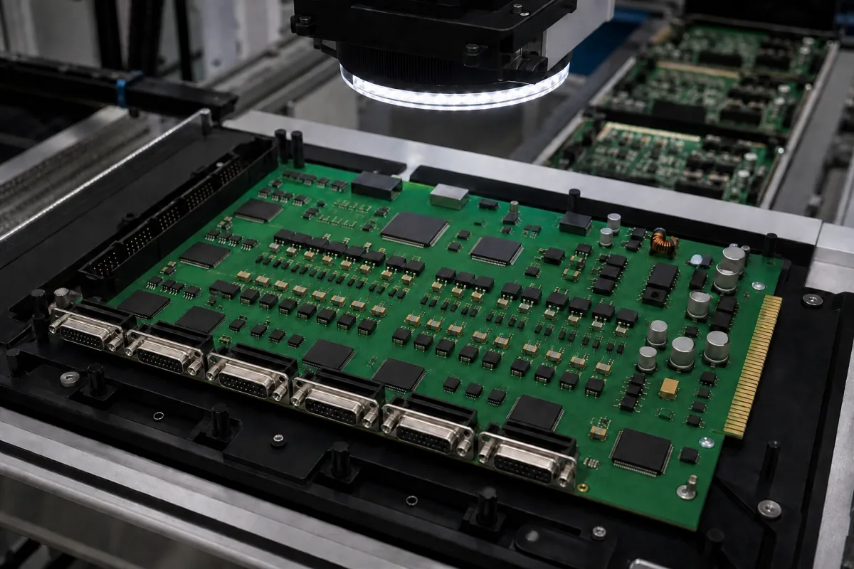
PCI and PCIe motion control card (plug-in board for a host PC)
PC-based machine control · PCI or PCIe slot, pulse-train or bus-master card, encoder inputs, wiring boards and host software
A PCI or PCIe motion control card is a circuit board installed in an expansion slot of an industrial PC, so that the PC's application software commands axis motion through the card while the card generates pulse trains or fieldbus frames for the servo or stepper drives. Ask three things first: which slot and bus it needs and which operating systems and libraries support it, whether it drives axes by pulse and direction or as a fieldbus master, and how its connectors, wiring boards and cables reach your drives, limit switches and encoders.
Motion control cards that plug into PCI or PCI Express slots of a host PC: pulse-train cards, fieldbus-master cards (EtherCAT, DMCNET and similar) and their wiring boards, cables and programming libraries. Standalone motion controllers and network-connected motion controllers are covered on the Motion controller page; servo drives, motors, complete CNC systems and the industrial PC itself are outside this page.
CNFX editorial research · Sources checked October 12, 2026 · 3 sources
Choose a pulse-train card or a fieldbus-master card for your slot
Advantech's PCI-1245L is a 4-axis pulse-train card for the Universal PCI V2.2 bus, accepting both 3.3 V and 5 V signal slots. It outputs pulse/direction or CW/CCW pulses at up to 1 Mpps, switchable by jumper between differential and single-ended, with 2-axis linear interpolation, T- and S-curve profiles, a step count range of ±2,147,483,646, a hardware emergency input and a watchdog timer. Advantech describes one unified user programming interface and graphical utility for all its motion controllers. [1]
A fieldbus-master card moves the axis count off the card's connectors. Zmotion's XPCIE1032H is a PCI Express EtherCAT card for 6 to 64 axes combining pulse and EtherCAT axes, with single-ended pulse/direction output at up to 500 kHz on its pulse axes, encoder measurement configurable as a handwheel input, and expansion to 512 isolated inputs and 512 outputs over EtherCAT; Zmotion pairs it with its MotionRT7 real-time kernel to run real-time control under Windows. [2] Delta's PCI-DMC-B01 acts as a DMCNET master controlling up to 12 stations for 12-axis motion, completes communication at a 1 ms cycle time, and offers 2 groups of real-time capture and compare for latching positions and triggering a camera at set pulse positions. [3]
Editorial note: a pulse card's axis count is fixed by its connectors and output channels, while a bus-master card's count depends on the network and the drives on it; give the supplier the axis count you need now and later, the drive models and their command interface, and the host PC's slot types before choosing.
Give the supplier the host PC and free slot types (PCI or PCIe, lane width), the operating system and programming language, the number and type of axes, drive models and their command interface (pulse/direction, CW/CCW, EtherCAT, other fieldbus), interpolation needs, encoder types, digital I/O count, position capture or compare needs, and the cable lengths to the drives.
02
Plan connectors, wiring boards, encoders and I/O
The PCI-1245L brings all four axes out on one 100-pin SCSI female connector; Advantech lists a 100-pin DIN-rail 4-axis wiring board, 50-pin 2-axis boards, 1–3 m cables and 2 m cables made up for specific servo drive families as accessories. Its encoder interface takes quadrature (A/B) or up/down signals at x1, x2 or x4 counting, an input range of 3–10 V, 2,500 VDC isolation, and up to 4 MHz in 4xAB mode (1 MHz for CW/CCW). Its local I/O lists machine interfaces LMT+, LMT− and ORG and servo-driver interfaces ALM and INP. [1]
The same datasheet gives the card's board-level conditions: 175 × 100 mm, typical 5 V at 0.6 A and maximum 5 V at 1 A, 0 to 60 °C operating, −20 to 85 °C storage and 5 to 95% RH non-condensing. [1] Zmotion states its XPCIE1032H general digital outputs can deliver up to 300 mA, enough to drive some solenoid valves directly. [2]
Editorial calculation: at the PCI-1245L's 1 Mpps maximum output and a drive set to 10,000 command pulses per motor revolution, the card can command at most 1,000,000 ÷ 10,000 = 100 rev/s, or 6,000 rpm; with a finer electronic gear the speed ceiling falls in proportion, so check pulse rate against the resolution and top speed you need. [1]
03
What sits on a motion card: bus interface, pulse channels, fieldbus port and encoder counters
Zmotion lists PCI and PCIe EtherCAT cards alongside its Ethernet cards and standalone controllers.
Zmotion Motion Control
Manufacturing site to be confirmed for the order
Lists PCI and PCIe EtherCAT motion control cards, including the XPCIE1032H for up to 64 pulse and EtherCAT axes, alongside Ethernet motion control cards and standalone controllers.
Explore company information and manufacturing capabilities, then discuss the scope of your project with a relevant supplier.
Share this page
Compiled and source-reviewed by the CNFX editorial team.
Each manufacturer above links to the page on that company's own website where the product is listed, with the date we checked it. How we source and review
· Page last updated 13 October 2026
Buyer questions
What is the difference between a pulse card and an EtherCAT card?
A pulse card such as Advantech's PCI-1245L drives a fixed number of axes (4) by pulse trains; a bus-master card such as Zmotion's XPCIE1032H reaches up to 64 axes over EtherCAT. [1][2]
How fast can a motion card output pulses?
Advantech lists up to 1 Mpps for the PCI-1245L; Zmotion lists 500 kHz for pulse axes on the XPCIE1032H. [1][2]
How is a motion card wired to the drives?
Through its connector and a terminal board; the PCI-1245L uses one 100-pin connector with DIN-rail wiring boards and drive-specific cables. [1]
Sources and what still needs a direct check
Sources checked 2026-10-12. Advantech, Zmotion and Delta Electronics are motion control makers describing their own PCI and PCIe cards.