Precision positioning stages · How accuracy, repeatability and backlash are measured, why makers' figures differ, Abbe error at the work point
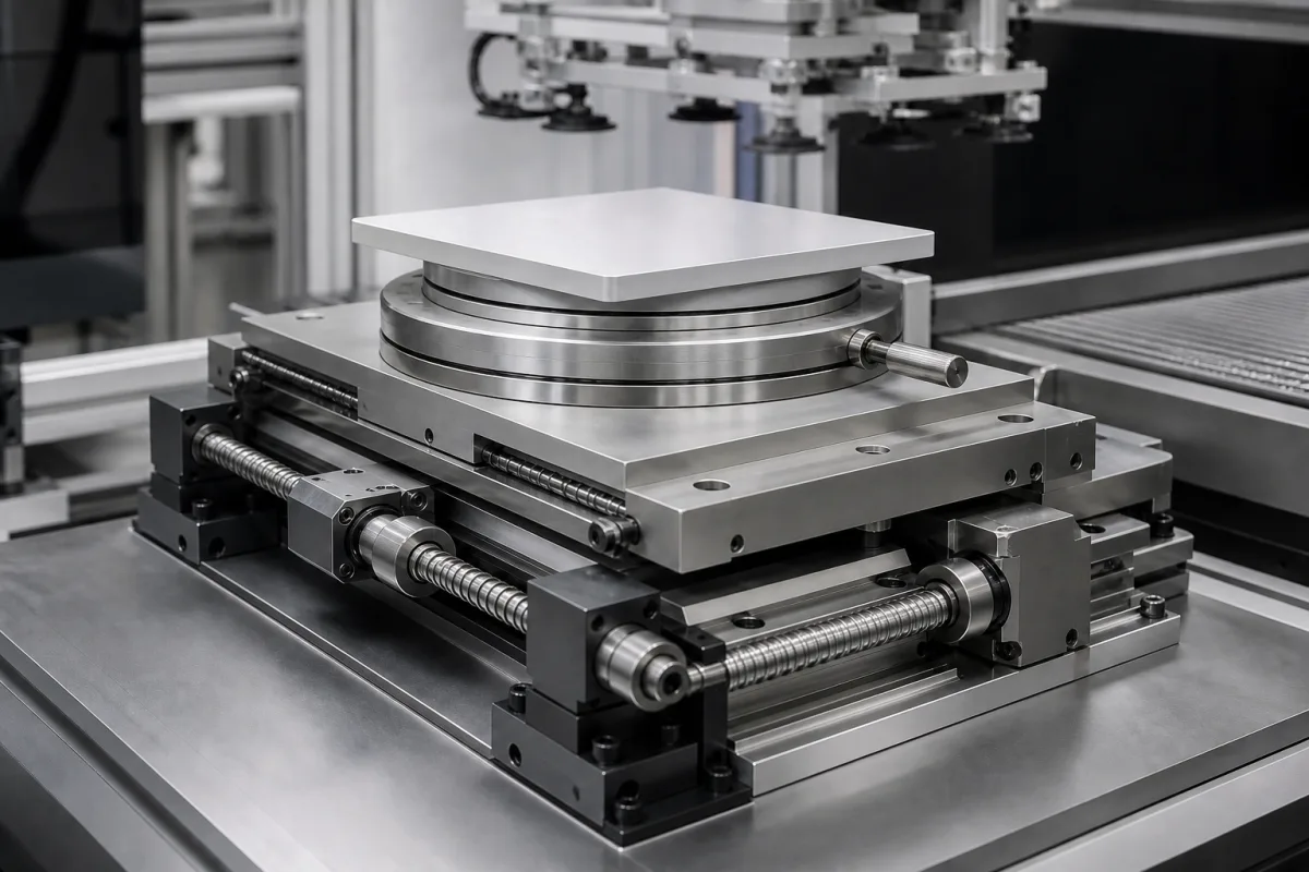
A positioning stage moves a load along one or more linear axes and in some designs a rotary axis, manually or by motor, so a part, tool or sensor can be placed precisely; the motorized XY-theta stage pictured stacks two ball-screw axes and a rotary table under a work plate. Ask three things first: how the supplier measured accuracy, repeatability and backlash (method, number of positions and cycles, and how many standard deviations), what angular errors the axes have and how far the work point sits from the measuring line, and what drive, guide and feedback deliver the figures.
Manual and motorized linear, XY, XYZ, rotary and tilt positioning stages for automation, inspection and optics. Complete gantry robots, machine tool tables, piezo nanopositioners and linear guides or ball screws sold as components are outside this page.
CNFX editorial research · Sources checked October 12, 2026 · 4 sources
Read accuracy, repeatability and backlash by how they were measured
PI's white paper on how it measures positioning axes bases its method on ISO 230-1 (2012), ISO 230-2 (2014) and ASME B5.54 (2005), adapted because those standards were written for larger machine tools. As standard it measures 20 target positions (the two ends plus 18 equally spaced), approaches each from both directions in a meandering cycle repeated five times, and records static positions with an interferometer, using an autocollimator for angular errors. [1]
From these data PI defines the mean bidirectional positioning error M (peak-to-peak of the mean curve), backlash B (largest difference between forward and backward means), bidirectional repeatability R = max over positions of [s↑ + s↓ + |B|; 2s↑; 2s↓], unidirectional repeatability as ± the largest standard deviation, and bidirectional positioning accuracy A as the range of the means plus and minus one standard deviation; it notes that A uses only one standard deviation, not two. It also states whether thermal drift or a linear correction has been removed from the raw data. [1]
Ossila, describing ISO 230-2 for its own stages, defines reversal error as the difference between forward and backward mean deviations, and positioning repeatability at a position as four times the sample standard deviation. [2] Editorial calculation: for an axis whose positioning scatter has a standard deviation of 0.5 µm, a one-sigma unidirectional figure is ±0.5 µm while a four-sigma ISO 230-2 figure is 2 µm, so ask which convention a datasheet uses before comparing suppliers.
Give the supplier the number of axes and travel of each, load mass and centre of gravity, required positioning accuracy and repeatability at the work point and the test method you will accept, speed and settling time, drive type (manual, stepper, servo, linear motor), feedback (motor encoder or linear scale), mounting orientation, environment and cable management.
02
Check angular errors and Abbe error at the work point
PI explains that an Abbe error occurs when an angular error (tilt of the moving platform) produces an error in a linear measurement, depending on the distance between the measuring point and the axes; it corrects its data to a point on the platform surface and notes that the resulting error for points at any distance from the platform can then be calculated. It names the angular errors of a linear X motion roll (EAX), pitch (EBX) and yaw (ECX), measured alongside positioning error and straightness. [1]
Editorial calculation: with a pitch error of 50 µrad, a work point 100 mm above the stage's measuring line moves about 100 mm × 50 × 10⁻⁶ = 5 µm along the axis, which can exceed the stage's own repeatability; stacking an XY stage and rotary table, as pictured, raises the work point and makes this offset larger.
PI also notes that thermal drift during measurement, from small temperature changes in the setup, can strongly affect results at the highest accuracies and may be corrected as a time-dependent straight line; its protocol states whether such a correction was applied. [1]
A catalogue stage shows the size of these angular errors. Zaber's LRQ150HL-E01T3A, a 150 mm ball-screw stage, lists unidirectional accuracy of 30 µm, repeatability below 5 µm, backlash below 25 µm, flatness below 25 µm and straightness below 20 µm, with pitch error 0.03° (0.523 mrad), roll 0.015° (0.262 mrad) and yaw 0.02° (0.349 mrad). It gives a 0.195 µm default microstep, 500 N peak and 200 N continuous thrust, a 1,000 N maximum centred load and a 110 mm/s maximum speed. [3]
Editorial calculation: that stage's 0.523 mrad pitch error, with a work point 50 mm above the carriage, gives an Abbe error of about 26 µm (50 mm × 0.523 × 10⁻³), close to its own 30 µm accuracy figure; keep the work point low or ask for accuracy measured at your working height. [3][1]
03
XY tables, turntables and tilt stages for optics in the listings
Listings include manual and motorized XY and XYZ stages, measuring turntables, linear positioning stages and modules, tilt and rotation stages and lab jacks for optics. Ask each supplier for a measurement report showing method, positions, cycles and sigma convention, plus pitch, yaw and straightness.
04
Ask which of the six error motions the test report covers
A 2018 open-access paper in Sensors by Liu and co-authors (National Cheng Kung University and National Chung Cheng University) notes that a linear precision stage has six geometric motion errors: positioning, horizontal and vertical straightness, pitch, yaw and roll. A conventional laser interferometer measures only one of these per experimental setup, so measuring them all is time-consuming. [4]
The authors tested a commercial linear-motor stage with 250 mm of travel and an optical encoder of 0.5 μm resolution, whose accuracy is given as ±1.7 µm (typ.). Their prototype recorded horizontal and vertical straightness errors of 19 µm and 16 µm, pitch of 24 arcsec, yaw of 10 arcsec, roll of 35 arcsec and a positioning error of 45 µm, which grew with position; in yaw, the prototype agreed with a reference laser interferometer to about 4 µm. [4]
Editorial calculation: 24 arcsec is about 116 µrad (24 × 4.848), so a work point 50 mm above the measuring line picks up about 5.8 µm of Abbe error (50 × 116 × 10⁻⁶ mm). Ask the supplier which of the six errors were measured, over what travel, with which instrument, and whether the values are measured or catalogue figures. [1]
05
Carriage, guides, drive and feedback behind the error figures
The carriage and guides set the pitch, yaw and straightness discussed above, so their rows are where angular-error limits belong in the order. [1]
Travel, accuracy method, load and angular-error entries
Write the measurement method and sigma convention next to every accuracy and repeatability value; without them two suppliers' numbers cannot be compared. [1][2]
Sets pitch, yaw, straightness; e.g. 0.523/0.349 mrad. [1][3]
Guide and angular error.
Material
Aluminium, steel or granite.
Material.
Weight (kg)
Moving and total mass.
Weights.
07
Send the axes, load and accuracy method together
Paste it into your enquiry below or into an email to a maker, then replace every bracket.
Axes: [X; Y; Z; rotary; tilt; travel each]
Load: [mass; centre of gravity; work point height]
Accuracy: [accuracy and repeatability at work point; test method; sigma]
Motion: [speed; settling; duty]
Drive: [manual; stepper; servo; linear motor]
Feedback: [encoder; linear scale]
Environment: [temperature; cleanliness]
Stage makers: lab XYZ stages, linear modules and optical mounts
JY Instrument lists manual and motorized XY and XYZ stages and turntables; Fuyu lists linear positioning stages and XY tables built from its linear modules; Winner Optics lists translation, rotation and tilt stages for optics.
Beijing JY Instrument Co., Ltd.
Manufacturing site to be confirmed for the order
Lists manual and motorized XY and XYZ stages and measuring turntables.
Explore company information and manufacturing capabilities, then discuss the scope of your project with a relevant supplier.
Share this page
Compiled and source-reviewed by the CNFX editorial team.
Each manufacturer above links to the page on that company's own website where the product is listed, with the date we checked it. How we source and review
· Page last updated 13 October 2026
Buyer questions
Why do repeatability figures differ between stage makers?
Methods differ: PI's accuracy figure uses one standard deviation, while Ossila describes ISO 230-2 repeatability as four standard deviations. [1][2]
What is backlash on a positioning stage?
PI defines it as the largest difference between the mean forward and backward positioning errors over the measured positions. [1]
What is Abbe error?
PI describes it as a linear error caused by an angular error of the moving platform, growing with distance from the measuring point. [1]
How large are pitch and yaw errors on a catalogue stage?
Zaber lists 0.523 mrad pitch, 0.262 mrad roll and 0.349 mrad yaw for its 150 mm LRQ150HL stage, with 30 µm unidirectional accuracy. [3]
How large are straightness and angular errors on a 250 mm linear stage?
In a 2018 Sensors paper by Liu and co-authors, a 250 mm linear-motor stage measured 19 µm horizontal and 16 µm vertical straightness, 24 arcsec pitch, 10 arcsec yaw and 35 arcsec roll. [4]
Sources and what still needs a direct check
Sources checked 2026-10-12. PI and Ossila are stage makers describing their own measurement methods; PI's is based on ISO 230 and ASME B5.54 with adaptations, and Ossila describes ISO 230-2.