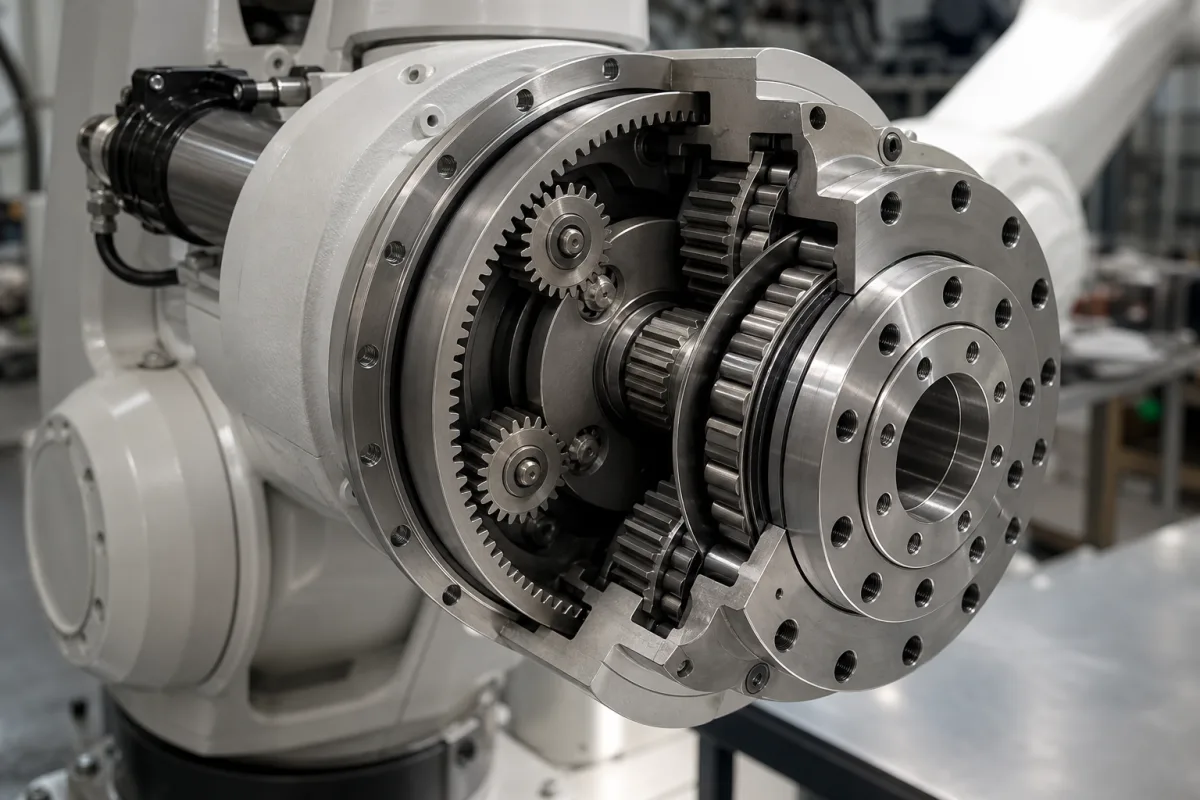
The illustrated joint opens up a reducer of this kind: a small input gear driving spur planet gears, a second stage behind them, and an output flange running on a large main bearing. Nabtesco's RV-N series serves as the example here, with rated torques from 245 to 28,000 N·m. What a robot builder needs from such a reducer is captured in a handful of datasheet lines: rated, acceleration and Torque Stop ratings, torsional and moment rigidity, allowed moment, and a life that falls steeply with torque.
Covers RV-type two-stage cycloidal reduction gears for robot joints: the rated, acceleration and Torque Stop ratings, torsional and moment rigidity, the main bearing's moment and load limits, hysteresis loss, and the life relation with average speed and torque. Strain-wave (harmonic) reducers are on Harmonic Drive Gears (5163) and their wave-generator bearing on Flexible Bearing (6787); planetary gear reducers on Planetary Gear Reducer (7893); industrial gear unit thermal rating on Gear Reducer (4301).
CNFX editorial research · Sources checked October 13, 2026 · 4 sources
Three torque ratings: rated, 2.5× for acceleration, 5× Torque Stop
Nabtesco lists each RV-N size with a rated torque, an allowable acceleration/deceleration torque and a 'Torque Stop' value. Its series page gives a shock load capacity of up to 5 times rated torque, hysteresis loss under 1 arcmin and efficiency of up to 85%.
For both sizes the acceleration torque is exactly 2.5 times and the Torque Stop value 5 times the rated torque, matching the series page's shock capacity of up to 5 times (1,960 / 784 and 3,920 / 784; 17,500 / 7,000 and 35,000 / 7,000; Editorial calculation). A robot axis is therefore checked three times: the averaged duty against rated torque, the peak of each acceleration ramp against 2.5×, and shock events such as an emergency stop against the 5× value.
Nabtesco attributes the compact design to the main bearing with integrated inner ring and the reinforced eccentric-shaft bearings; the datasheets list an allowed moment and radial and axial loads for that bearing.
Item
RV-80N
RV-700N
Rated torque
784 N·m
7,000 N·m
Allowable acc./dec. torque
1,960 N·m
17,500 N·m
Torque Stop
3,920 N·m
35,000 N·m
Max. speed (depends on ratio)
88 rpm
19 rpm
Ratios
41, 81, 101, 129, 141, 171
105, 118, 142.44, 159, 183, 203.52
Hysteresis loss
< 1 arcmin
< 1 arcmin
Outer diameter
189 mm
395 mm
Values are Nabtesco's for these two sizes; check the ratio-specific data and the conditions behind each torque in the catalogue.
02
Torsional 212 N·m/arcmin, moment 1,190 N·m/arcmin, and what they mean at the tool
The same datasheets give the stiffness of the output against twist and against tilting, and the loads the integral main bearing accepts.
Torsional rigidity sets how far the output twists under a load change. On the RV-80N, a 100 N·m change twists it by 100 / 212 = 0.47 arcmin, which moves a point 1 m from the joint axis by about 0.14 mm (Editorial calculation, linear model). At full rated torque the twist on the same linear model is 3.7 arcmin.
The moment rigidity and allowed moment matter where the arm's weight hangs off the reducer: a 40 kg link whose centre of mass sits 0.5 m out from the bearing loads it with about 40 × 9.81 × 0.5 = 196 N·m (Editorial example), well inside the RV-80N's 2,150 N·m.
Item
RV-80N
RV-700N
Torsional rigidity
212 N·m/arcmin
2,600 N·m/arcmin
Moment rigidity
1,190 N·m/arcmin
9,000 N·m/arcmin
Allowed moment
2,150 N·m
15,000 N·m
Radial load
14,163 N
46,368 N
Axial load
6,530 N
44,000 N
The linear twist calculation ignores the low-load region around zero where hysteresis and lost motion dominate; the catalogue's rigidity curve should be used for that range.
03
Life falls with average torque to the 10/3 power
FANUC's patent US 8,731,886 (2014) on simulating robot reducer life sets out the calculation a robot controller can run from the axis's speed and torque history.
The 10/3 exponent makes torque the dominant lever. Running at 80% of rated torque instead of 100% multiplies life by (1/0.8)^(10/3) = 2.1; running at 120% cuts it to 0.54 of the rated value (Editorial calculation). Halving the average speed doubles it. Because the mean is weighted to the 10/3 power, short high-torque segments of a cycle count far more than their share of time (Editorial reading of the formula).
The patent also flags program lines where the load exceeds a reference value, so the motion can be rewritten before the reducer's life is used up.
Step in the patent
What is calculated
1
Average speed Nm: sum of ti·Ni over the sum of ti, from sampled speed Ni per period ti
2
Average torque Tm: the 10/3-power mean of torque, weighted by ti·Ni
3
Reducer life from rated speed N0 and rated torque T0 against Nm and Tm, with torque entering through (T0/Tm)^(10/3); the patent notes the 10/3 multiplier varies with the type of reducer
4
Divide by the operating ratio, e.g. 8 h a day gives 8/24 = 1/3
The rated life and rated speed behind N0 and T0 come from the reducer maker's catalogue; this page does not state them.
04
What to give a reduction gear supplier for a robot joint
Paste it into your enquiry below or into an email to a maker, then replace every bracket.
Give the joint's torque–speed cycle with acceleration peaks, emergency-stop braking torque, the arm's moment and radial and axial loads on the output bearing, required ratio, stiffness at the tool, allowable hysteresis or lost motion, target life in hours and operating ratio, and mounting space. Ask for rated, acc/dec and Torque Stop ratings and what each covers, torsional and moment rigidity with the rigidity curve, allowed moment and bearing loads, efficiency, and the life formula and rated values the supplier uses.
Explore company information and manufacturing capabilities, then discuss the scope of your project with a relevant supplier.
Share this page
Compiled and source-reviewed by the CNFX editorial team.
Each manufacturer above links to the page on that company's own website where the product is listed, with the date we checked it. How we source and review
· Page last updated 13 October 2026
Buyer questions
What are the torque ratings of an RV-80N?
Nabtesco lists 784 N·m rated, 1,960 N·m allowable acceleration/deceleration torque and a Torque Stop value of 3,920 N·m. [2]
How stiff is an RV reducer?
The RV-80N is rated 212 N·m/arcmin torsional and 1,190 N·m/arcmin moment rigidity; the RV-700N 2,600 and 9,000 N·m/arcmin. [2][3]
How does torque affect reducer life?
In FANUC's patent US 8,731,886, life is computed with torque entering as (T0/Tm)^(10/3); running at 80% of rated torque roughly doubles life (Editorial calculation). [4]
What range of sizes does the RV-N series cover?
Nabtesco gives rated torques from 245 N·m to 28,000 N·m, shock capacity up to 5 times rated torque, hysteresis loss under 1 arcmin and efficiency up to 85%. [1]
Sources and what still needs a direct check
Sources checked 2026-10-13. Nabtesco's RV-N series page and two size datasheets, and a FANUC patent on estimating reducer life in a robot controller.