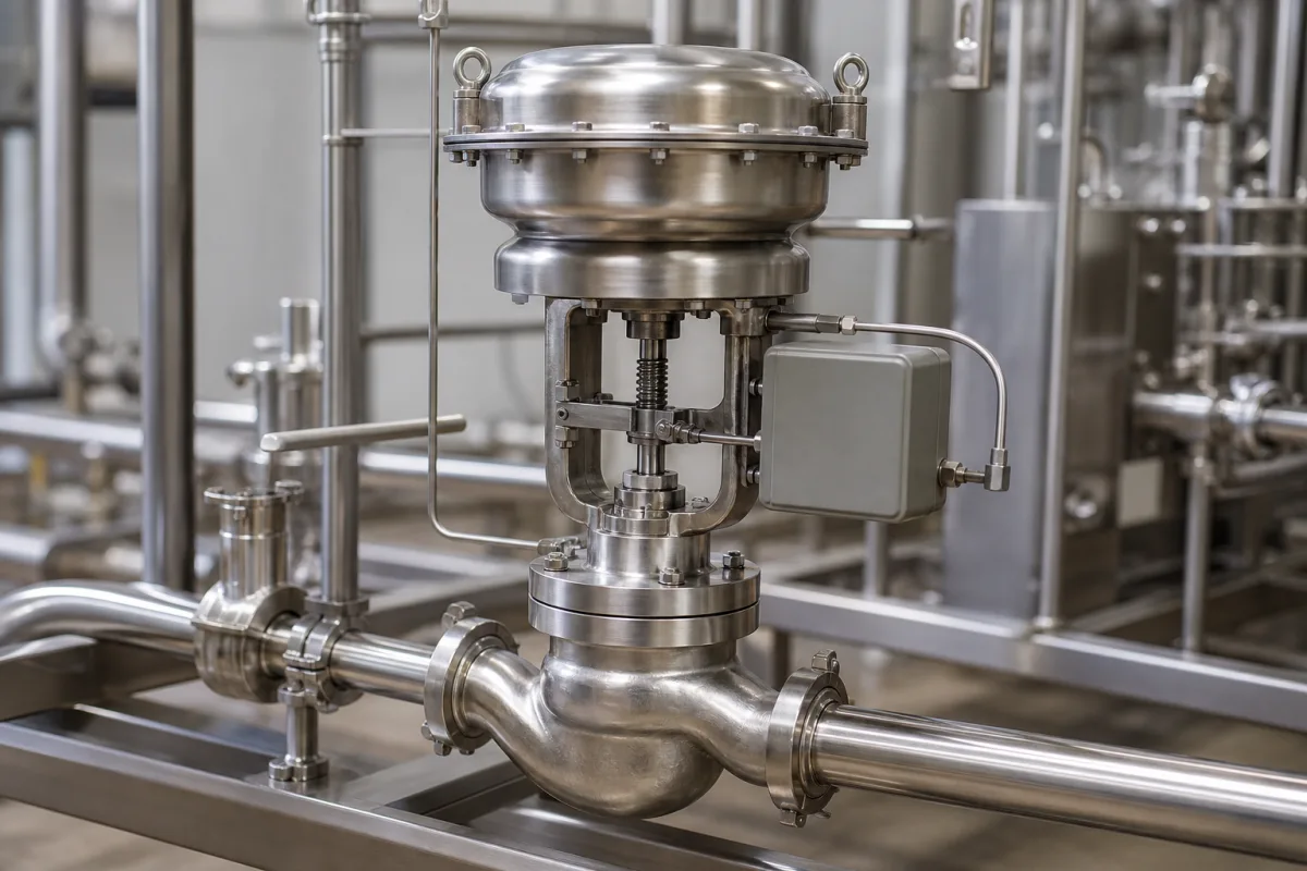
Hygienic pneumatic regulating valve for food, beverage and pharmaceutical lines: stainless body, actuator and positioner
Hygienic seat-type control valve with pneumatic actuator and positioner · Ra ≤0.8 µm wetted surfaces, clamp bonnet, 3-A and EHEDG versions, Kv sizing at mid-stroke, diaphragm or air/spring actuator
A hygienic pneumatic regulating valve is a seat-type control valve built for product contact: a stainless body free of dead spaces, clamp or weld ends for sanitary tube, a plug that throttles flow under a pneumatic actuator, and a positioner that sets the stroke from a 4–20 mA or similar signal. It is used to control flow, pressure, temperature or mixing in dairy, food, beverage and pharmaceutical plants and is cleaned in place and, where the process requires it, sterilised in place. Decide three things first: the surface finish and hygienic certification of the wetted parts, the Kv needed at the working point, and the actuator type, fail position and positioner.
Pneumatically actuated, seat-type control (regulating) valves with hygienic stainless bodies for food, beverage, dairy, brewing and pharmaceutical processes, including their actuators and positioners. General industrial pneumatic globe control valves, their sizing and trim are covered on the Pneumatic globe control valve page; plug designs on the Control valve plug page; micro-flow valves on the Low-flow (micro-flow) pneumatic flow control valve page; electric-actuator flow loops on the Liquid flow controller with electric valve actuator page; and weir-type sanitary diaphragm valves on the Sanitary diaphragm valve for dairy processing page. Ladle slide gates and self-acting pressure regulators are outside this page. Two neighbouring parts have pages of their own: the head that drives a weir-type diaphragm valve on the Pneumatic actuator for sanitary diaphragm valves page, and positioners chosen by signal, air delivery and diagnostics on the Valve controller (valve positioner) page.
CNFX editorial research · Sources checked October 12, 2026 · 3 sources
Ra ≤0.8 µm wetted surfaces, clamp bonnet and 3-A or EHEDG versions
SAMSON's Type 3347 hygienic angle valve, offered in DN 6 to 150 for up to 63 bar and –10 to 150 °C, has a stainless body free of dead cavities, an internal surface finish of Ra ≤0.8 µm, wetted seals complying with FDA rules and Regulation (EC) No. 1935/2004, and a clamp joint between body and bonnet so the bonnet lifts off for cleaning; it is suited to cleaning-in-place and sterilisation-in-place. [1] Alfa Laval's Unique RV-ST regulating valve uses 1.4404 (316L) for wetted steel parts with a polished internal finish of Ra <0.8 µm and EPDM plug and product seals, with HNBR or FPM as options. [2]
SAMSON lists polished body options with internal finishes down to Ra ≤0.4 µm, states that all listed end connections comply with 3-A rules (with 3-A seals fitted on site by the user), and holds EHEDG Type EL Class I certification for the bar-stock body in DN 15 to 125 with PTFE stem guide. End connections include DIN 11866, ISO 1127, ISO 2037, ASME BPE and BS 4825 welding ends, rated to 16 bar or, in high-pressure versions, 40 bar up to DN 100. [1]
SAMSON recommends installing the valve upright with the actuator on top, because other positions do not let the pipeline drain fully, and offers a steam barrier that sterilises the plug stem with steam or a sterile fluid. [1] GEA's VARIVENT control valves put the control cone and seat in a dead-zone-free, fully cleanable housing, with an open lantern so a failing stem seal shows as a visible leak. [3]
Give the supplier the product and CIP/SIP media and temperatures, required wetted materials and Ra finish, the hygienic certification needed (3-A, EHEDG) with its certificate number, the tube standard and end connection, the installed orientation and whether a steam barrier on the stem is needed.
02
Kv at 50% stroke: the Alfa Laval 60 m³/h example and SAMSON's Kvs 0.4–200 range
Alfa Laval's sizing example for the Unique RV-ST takes 60 m³/h of water from 3 bar to 1.5 bar: ΔP is 1.5 bar, so Kv = 60 ÷ √1.5 ≈ 49. Reading the Kv-stroke diagrams, the 2-inch valve is chosen because the Kv 49 line crosses its curve closest to the 50% stroke operating point. [2]
Alfa Laval recommends a maximum flow velocity of 5 m/s in tubing and valves, and notes that its 1½" to 4" sizes have a plug seal so the valve also shuts off, while the 1" size does not. [2] SAMSON recommends a V-port plug instead of a parabolic plug for DN 40 to 65 above 10 bar and for DN 80 to 125 above 6 bar. [1]
GEA states that an exchangeable seat ring and matching cone let more than one Kvs value be fitted per nominal width, so the valve can be re-trimmed later when operating conditions change. [3] Editorial note: send the minimum, normal and maximum flow with the inlet and outlet pressure at each, so the supplier can check that all three fall inside the trim's usable stroke and not only the design point.
Valve
Kv or Kvs range
Other limits
SAMSON Type 3347, cast body, DN 25–100
Kvs 0.4–160 (Cv 0.5–190)
Equal-percentage or linear; rangeability 50:1, or 25:1 for some seat sizes [1]
Kv 49 crosses one curve on 2-inch and 2½-inch sizes, three on 3-inch and 4-inch
Max 10 bar product, full vacuum; 1" size without plug seal [2]
GEA VARIVENT type S or P
More than one Kvs per nominal width via exchangeable seat ring and cone
Linear or equal-percentage cone; soft or metal seal [3]
03
Diaphragm or air/spring actuator, 24 VDC positioner and fail-open or fail-closed springs
GEA builds its VARIVENT control valve as type S with a diaphragm actuator and positioner, described as designed for fast, high-precision control, or type P with an air/spring actuator and T.VIS P-15 positioner, which works at a slightly slower speed; the two differ only in the actuator and can be converted from one to the other later. [3]
Alfa Laval's RV-ST takes 5 to 7 bar control air; its positioner runs on 24 VDC ±10%, accepts a 0/4–20 mA or, on the display version, 0/5–10 V setpoint, uses contact-free position detection and is rated IP65 and IP67 for 0 to 55 °C ambient. [2]
SAMSON's Type 3347 is combined with Type 3271 or 3277 diaphragm actuators or the Type 3379 piston actuator, and the spring arrangement sets the fail-safe position on loss of air: actuator stem extends to close the valve, or retracts to open it. [1] Editorial note: choose fail-closed or fail-open from what must happen to the product line on loss of air, and state it with the valve, since it fixes the actuator spring build.
04
Process, hygiene and control data for a hygienic regulating valve
Paste it into your enquiry below or into an email to a maker, then replace every bracket.
Duty: [flow, pressure, temperature or mixing control; product]
Flows: [min, normal, max in m³/h; inlet and outlet pressure at each]
Hygiene: [wetted material; internal Ra; 3-A or EHEDG certificate; seal material; CIP/SIP temperatures]
Connection: [tube standard; clamp or weld end; size]
Actuator: [diaphragm or air/spring; fail-closed or fail-open; air supply pressure]
Positioner: [signal 4–20 mA or fieldbus; supply voltage; feedback; IP rating]
2 companies list this product among what they make. Company figures are quoted from each
company's own website; every card states where the relationship came from.
Donjoy Technology
Manufacturing site to be confirmed for the order
Lists pneumatic diaphragm-type regulating valves, including aseptic and proportional aseptic control valves for biopharmaceutical and food processing, with valve positioners and control units.
Explore company information and manufacturing capabilities, then discuss the scope of your project with a relevant supplier.
Share this page
Compiled and source-reviewed by the CNFX editorial team.
Each manufacturer above links to the page on that company's own website where the product is listed, with the date we checked it. How we source and review
· Page last updated 13 October 2026
Buyer questions
What surface finish do hygienic control valves have?
SAMSON's Type 3347 has an internal finish of Ra ≤0.8 µm as standard with polished options down to Ra ≤0.4 µm; Alfa Laval's RV-ST is polished to Ra <0.8 µm. [1][2]
How is a hygienic regulating valve sized?
Alfa Laval calculates Kv = Q ÷ √ΔP (60 m³/h at 1.5 bar gives Kv 49) and picks the size whose curve crosses that Kv nearest 50% stroke. [2]
What is the difference between GEA control valve types S and P?
Type S uses a diaphragm actuator and positioner for fast, high-precision control; type P uses an air/spring actuator with a T.VIS P-15 positioner and works slightly slower. [3]
What leakage class does a hygienic control valve reach?
SAMSON lists class IV for metal-seated and class VI for soft-seated plugs on the Type 3347. [1]
Sources and what still needs a direct check
Sources checked 2026-10-12. SAMSON, Alfa Laval and GEA are valve makers describing their own hygienic control valves; certification statements (3-A, EHEDG) are theirs and should be checked against the certificate for the exact build ordered.