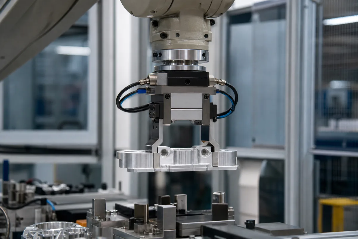
The gripper in the illustration hangs from a robot flange: a pneumatic parallel gripper with cables to its position sensors, and two custom-machined fingers closing on a cast aluminium part above its fixture. The gripper body is bought from a catalogue; the fingers are designed for this part, and the sensors decide whether the robot knows it really has it. Those two choices are where a gripper cell succeeds or drops parts.
Covers the job-specific parts of robot finger grippers: finger and fingertip design (form-fit versus force-fit, contact materials), moment limits for custom fingers, fixing custom, plastic and additively made fingers, and sensing jaw position and part presence (magnetic, inductive, analog). Gripping-force sizing, jaw length and air-failure behaviour, robot flange and payload matching are on Robot end effectors: finger grippers; vacuum gripper units are on Specialized end effector; soft and vacuum grippers are outside this page.
CNFX editorial research · Sources checked October 13, 2026 · 3 sources
OnRobot's 3FG25 three-finger gripper data sheet puts numbers on the difference between gripping by friction and gripping by shape.
A form-fit grip, where the fingertips locate on features of the part, carries 25 kg against 15 kg by friction alone on the same gripper, about 1.7 times as much (Editorial calculation). OnRobot's X-shaped fingertips combine both for round parts with collar-like features. The machined fingers in the illustration follow the same idea, closing into pockets in the casting rather than pressing on flat faces.
The torque limits apply when custom fingers or fingertips are fitted: 40 Nm around X and Y at the finger platform and 8 Nm at the finger end, measured in OnRobot's coordinate system. Longer or heavier custom fingers use up those limits through the part's weight and acceleration. Fingertip choice changes friction: steel, NBR or knurled tips; OnRobot's knurled set raises friction and payload for raw and oil-coated CNC parts but may mark the material.
3FG25 (OnRobot)
Value
Payload, force-fit grip
15 kg (10 kg flexible grip)
Payload, form-fit grip
25 kg
Gripping force
50–450 N grip; 50–300 N flexible grip
Diameter repeatability
0.1 mm typ., 0.2 mm max
Max torque on finger platform (X, Y)
40 Nm
Max torque at finger end (X, Y)
8 Nm
Holds workpiece on power loss
Yes
Ask for the finger drawing showing which part features the fingers locate on, the resulting moment at the finger platform under acceleration, and the fingertip material against the part's finish.
02
Fixing custom, plastic and printed fingers
SCHUNK's short manual for eGRIP fingers, its additively made custom fingers, sets out the mounting rules.
Use every fixing hole in the gripper's base jaws, with property class 12.9 screws to SCHUNK's table. For plastic fingers, use washers to DIN EN ISO 7090, because the plastic settles and the screw preload can drop sharply, and add a medium-strength threadlocker; on PGN-plus grippers, use centring sleeves. The fingers and their screws are wear parts with limited life (cracking, for example), to be checked regularly by trained staff and replaced when needed. SCHUNK also warns that powder particles can come loose from additively made fingers, and that the fingers must not be reworked.
The permitted screw torque for plastic (PA12) fingers is a small fraction of that for steel or aluminium fingers on the same gripper.
SCHUNK PGN-plus size
Screws
Max torque, PA12 fingers
Max torque, steel/aluminium fingers
40
4 × M2.5
0.15 Nm
0.68 Nm
64
4 × M4
0.6 Nm
3.1 Nm
100 / 125
4 × M6
1.8 Nm
10 Nm
On M6, the PA12 limit is 18% of the metal-finger torque (Editorial calculation). Ask for finger material, fixing screws and torques, and the inspection interval for printed or plastic fingers.
03
Knowing what the jaws did
Balluff's white paper on gripper sensing lists the three things a controller wants to know: jaw open, closed or closed on a part; the jaws' actual position; and whether a part is in the jaws.
The indirect method puts magnetic field sensors in the slots of the gripper's cylinder to detect the magnet ring on the piston; two or three sensors give fully open, fully closed and closed on a part, and each can be slid along the slot to set its switch point. The direct method uses miniature inductive sensors, down to 3 mm diameter and 6 mm long, on the jaws or on metal targets fixed to them, where the piston has no magnet or the cylinder wall is ferromagnetic.
An analog sensor gives the jaw position continuously: an analog inductive sensor reading a sloped target on the jaw, or a magnetoinductive sensor on the cylinder giving 4–20 mA or 0–10 V. That allows parts of different sizes to be told apart, soft parts to be squeezed only as much as needed, and slow jaw movement from an air leak or worn mechanism to be flagged for maintenance; being absolute, it reports position after a power loss without re-homing. For metal parts, flat inductive sensors in the jaws confirm a part is present; Balluff stresses shock-rated housings and flex-rated cables.
Signal (Balluff)
Sensor
Jaw open / closed / closed on part
Magnetic field sensors in cylinder slots (indirect) or inductive sensors on jaws (direct)
Actual jaw position
Analog inductive with sloped target, or magnetoinductive linear sensor
Part present
Inductive flat-pack in the jaw (metal parts) or photoelectric through-beam
Ask which states are sensed, how the closed-on-part switch point is set for your part's tolerance, and whether an analog signal is available for size checking and wear detection.
04
What to give a gripper supplier for custom fingers
Paste it into your enquiry below or into an email to a maker, then replace every bracket.
Send the part drawing with features the fingers may locate on, its mass, finish and tolerance, robot accelerations, and the cycle's pick and place positions. Ask for the finger design and material, fingertip type, the resulting moments against the gripper's limits, fixing screws and torques, sensor arrangement for open, closed, on-part and part-present, and the inspection and replacement interval for the fingers.
1 company lists this product among what they make. Company figures are quoted from each
company's own website; every card states where the relationship came from.
Changzhou Heli Automation Technology Co., Ltd.
TBC
Heli Automation's site lists robotic grippers alongside compensation units, quick-change modules, rotary units and six-axis force-torque sensors; ask for finger interface dimensions and sensor options.
Explore company information and manufacturing capabilities, then discuss the scope of your project with a relevant supplier.
Share this page
Compiled and source-reviewed by the CNFX editorial team.
Each manufacturer above links to the page on that company's own website where the product is listed, with the date we checked it. How we source and review
· Page last updated 13 October 2026
Buyer questions
How much more does a form-fit grip carry?
OnRobot rates its 3FG25 at 25 kg form-fit against 15 kg force-fit. [1]
What limits custom finger design?
The gripper's allowed moments: for the 3FG25, 40 Nm at the finger platform and 8 Nm at the finger end around X and Y. [1]
How should plastic fingers be fixed?
SCHUNK requires all fixing holes, ISO 7090 washers, medium threadlocker and much lower torques than for metal fingers, because plastic settles and loses preload. [2]
How does the robot know it has the part?
Balluff describes a third magnetic sensor position for closed-on-part, analog jaw position, or an inductive sensor in the jaw for metal parts. [3]
Sources and what still needs a direct check
Sources checked 2026-10-13. A gripper maker's data sheet, a second gripper maker's finger-mounting manual and a sensor maker's white paper.