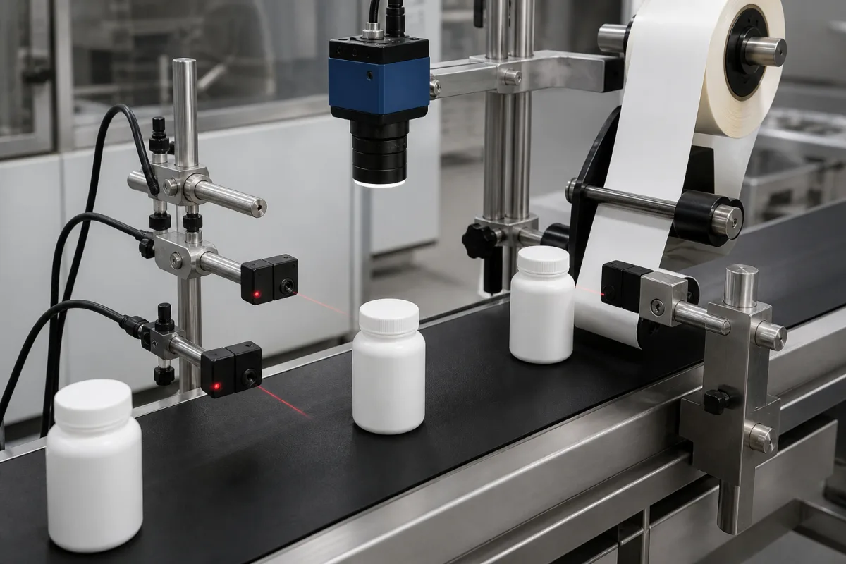
Product sensor, label sensor and encoder on a labeller
The station in the illustration has two red-light product sensors on a post beside the conveyor, a camera above the line, the label web running off a roll to a dispensing edge, and a second sensor near the web. Together with an encoder on the conveyor, these make up the sensing system. A label lands in the right place only if the system knows when the product passed, where the next label edge is, and how fast the line is moving at that moment.
Covers the sensing and timing chain of label applicators and print-and-apply units on conveyors: product sensors and their distance to the dispensing edge, label sensors at the peel edge, conveyor encoders for speed following and position compensation, compensation of sensor response delay, and the limits on placement accuracy. Fork, photoelectric and ultrasonic label gap sensors as devices are on Label sensor; labelling machines as a whole, general photoelectric sensors and code readers have their own pages; fibre Bragg grating sensing systems are outside this page.
CNFX editorial research · Sources checked October 12, 2026 · 3 sources
Harland Machine Systems' patent application EP 0 441 617 describes the conventional arrangement it set out to improve.
A product sensor detects the product on the conveyor and the label-carrying web is accelerated to conveyor speed; a label sensor at the beak, where the label separates from the web, detects the label and decelerates the web so that the next label waits in position; a shaft encoder on the conveyor detects speed changes. The patent says labels could be misplaced to an unacceptable degree because product speed varied and the sensor position had to be adjusted by hand to compensate, and because detecting a label by its leading or trailing edge misplaces labels when label or product size varies.
Its answer is to work from a datum between the label's front and rear edges and to vary when the web acceleration starts (and the deceleration), so label and product speeds match at application and placement stays constant whatever the label or product speed or spacing. Each encoder pulse represents a proportional movement of the conveyor and product, and the control counts pulses to time the application.
Element
Job (EP 0 441 617)
Product sensor
Detects the product; starts the count to application
Label sensor at the beak
Detects the label on the web; stops it ready for the next product
Shaft encoder on the conveyor
Pulses in proportion to conveyor and product movement
Control
Times web acceleration and deceleration from pulse counts
The camera above the line in the illustration verifies the applied label after the event; it does not take part in timing. Ask which sensor triggers the dispense and what the camera checks.
02
Keeping position when line speed changes
Carl Valentin's note on the encoder option for its ILX V print modules shows the effect in numbers.
In wipe-on labelling the label is peeled at a dispensing tongue and wiped onto the passing product, and to prevent wrinkling the feed speed must match the conveyor speed. With an encoder the module measures conveyor speed continuously and selects the next lower available speed, for example 150 mm/s for a measured 156 mm/s, within 50 to 400 mm/s.
Position is the second problem. The product sensor sits a fixed distance before the dispensing edge; Carl Valentin's example is 200 mm. If the conveyor goes from 150 to 200 mm/s, the label lands 66 mm further along the product unless the timing is corrected. In encoder mode the module measures the distance the product actually travels and adjusts the print timing; the print offset must be at least 20 mm, compensation works only over a limited range, and the offset must never be so long that two products sit between sensor and dispensing edge at once.
Carl Valentin adds that the gap between dispensing tongue and product, label size and product properties still affect accuracy, so small shifts can remain with an encoder. HERMA's 500 applicator includes a master encoder function as standard and labels at 30 to 200 m/min.
Line speed
Product travel per 1 ms of timing error
150 mm/s (Carl Valentin example)
0.15 mm
30 m/min (0.5 m/s)
0.5 mm
200 m/min (3.33 m/s, HERMA 500 maximum)
3.3 mm
Editorial calculation: a fixed delay of 200 mm ÷ 150 mm/s = 1.33 s at 200 mm/s carries the product 267 mm, 67 mm further, matching Carl Valentin's 66 mm. The table shows why sensor and controller timing matter more at high line speed. Ask for the placement tolerance at your minimum and maximum line speeds.
03
Correcting the sensors' own delay
EP 0 441 617 also provides for the inherent response delay of the label and product sensors. A product-delay compensation device introduces a corrective count, converted into encoder pulses, which is subtracted from the count held in the application counter; a label-delay compensation device does the same for the label sensor. Because the correction is in encoder pulses rather than time, it stays a fixed distance whatever the speed (Editorial reading: a fixed time delay would correspond to more pulses at higher speed, so a pulse correction set at one speed is exact only at that speed).
A speed-compensation device in the same control calculates how many counts to add to or remove from the next application to keep placement consistent.
Ask whether the labeller compensates product and label sensor delay, whether in time or in encoder counts, and whether the setting must be changed for a different line speed.
04
What to give a labeller supplier about sensing
Paste it into your enquiry below or into an email to a maker, then replace every bracket.
State line speed range, product size range and spacing, label size and position tolerance, product material and colour against the conveyor, whether labels are printed on demand, and whether a verification camera is wanted. Ask for the product sensor type and distance to the dispensing edge, the label sensor type, whether a conveyor encoder or master encoder is used, how speed and position are compensated and over what range, how sensor response delay is corrected, and the measured placement tolerance across the speed range.
Explore company information and manufacturing capabilities, then discuss the scope of your project with a relevant supplier.
Share this page
Compiled and source-reviewed by the CNFX editorial team.
Each manufacturer above links to the page on that company's own website where the product is listed, with the date we checked it. How we source and review
· Page last updated 13 October 2026
Buyer questions
Why does the label move along the product when the line speeds up?
The product sensor sits a fixed distance before the dispensing edge; Carl Valentin's example shows a 66 mm shift when speed rises from 150 to 200 mm/s with the sensor 200 mm away, unless an encoder corrects the timing. [2]
What does a conveyor encoder do on a labeller?
It reports conveyor movement so the label feed speed matches the conveyor and the dispense timing follows actual product travel (Carl Valentin; EP 0 441 617). [2][1]
Can sensor response delay be corrected?
EP 0 441 617 subtracts a corrective count, in encoder pulses, from the application counter for both product and label sensors. [1]
How fast do label applicators run?
HERMA lists 30 to 200 m/min for the HERMA 500, with a master encoder function as standard. [3]
Sources and what still needs a direct check
Sources checked 2026-10-12. A labelling control patent application, a print-module maker's encoder note and a label applicator maker's specification.