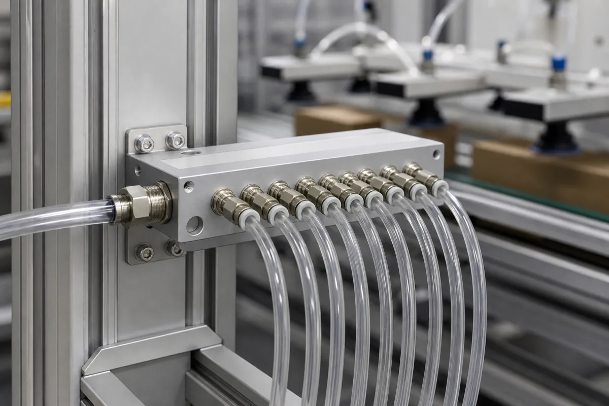
Vacuum manifold (block distributor) for multi-cup vacuum grippers
Block distributor for multi-cup grippers · one large inlet to a row of small outlets, thread pairs, dead volume and per-cup leak control
A vacuum manifold in an end-of-arm tool is a machined block, in the products reviewed here anodised aluminium, with one large threaded inlet from the ejector or pump and a row of smaller threaded outlets, each fitted with a push-in fitting and a hose to one suction cup. It decides three things on the gripper: whether every cup gets a hose of the bore it was sized for, how much air volume the vacuum generator has to pull out before the part lifts, and whether one cup that misses the part starves the others.
Block-type vacuum distributors (manifolds) that connect two or more suction cups or vacuum grippers to one vacuum generator on pick-and-place, palletising and sheet-handling tools, with their fittings, plugs and per-cup check valves or flow restrictors. Vacuum hold-down tables for CNC routers and flatbed printers, with their plenum and zone valves, are covered on the Vacuum table for CNC and flatbed machines page. Ejector manifolds with built-in valves, laboratory solid-phase-extraction (SPE) vacuum manifolds and high-vacuum chamber manifolds are outside this page.
CNFX editorial research · Sources checked October 12, 2026 · 8 sources
Main-inlet and outlet thread pairs, and how many outlets to buy
VMECA states the reason the part exists: on vacuum circuits with more than one suction cup it is important to keep the pipe bore, so its manifolds bring multiple connections back to one large BSP connection. They are made from lightweight anodised aluminium and ship with mounting brackets and one end plugged. [1]
Outlets on these blocks are ordered in multiples of four, and the VTDF drawing gives the block length as n × 17 mm plus a fixed allowance for G1/8 outlets, n × 22 mm for G1/4 and n × 25 mm for G3/8, so larger outlet threads make a longer block for the same count. [1]
Schmalz's sheet-handling example shows how the count works out in practice. Six SUF 90 suction cups each take an 8/6 mm hose, so the distributor chosen is a VTR G3/8-IG 9xG1/4 in aluminium, 116 × 39 × 24 mm, with one G3/8 female inlet and nine G1/4 female outlets. Six outlets get G1/4 push-in fittings for 8 mm hose and the three spare outlets are closed with G1/4 sealing screws. [4]
Editorial note: buying the next block size up and plugging the spare outlets, as in that example, leaves room to add cups later; every open outlet left unplugged is a leak.
VMECA series
Where the outlets are
Main inlet → outlet threads listed
Maximum outlets
VTDF
Top face
G3/8 → G1/8; G1/2 → G1/8 or G1/4; G3/4 → G1/8, G1/4 or G3/8 [1]
Give the supplier the main inlet thread, outlet thread and count, which faces the outlets go on, the hose outside diameter for each push-in fitting, the number of spare outlets to plug, mounting (bracket or through-holes), material and finish, and whether check valves or restrictors are to be fitted at the cups or in the block.
02
Count the manifold's internal volume in the pick-up time
Schmalz calculates evacuation time from the total volume that has to be pumped down: suction cups, mounting elements, hoses, the distributor and any filter or valve. In its example of six cups the volumes add to 6 × 35 cm³ + 6 × 9.5 cm³ + 6 × 43 cm³ + 1 × 38.5 cm³ = 564 cm³, and with a 6.95 m³/h generator pulling from 1,013 mbar to 400 mbar absolute, t = (V × ln(Pa/Pe) × 1.3) / suction rate gives 0.35 s. [5]
Editorial calculation: the single 38.5 cm³ term, which sits in the position of the distributor in Schmalz's formula, is 38.5 / 564 = 6.8% of the volume pumped, against 258 cm³ (46%) for the six hoses. A shorter hose run to each cup cuts pick-up time more than a smaller block does, but an oversized block with long internal galleries adds to every cycle.
The same worked example sizes the vacuum generator that feeds the manifold inlet by cup diameter, for smooth, air-tight parts: 8.3 l/min per cup up to 60 mm, 16.6 l/min up to 120 mm, 33.3 l/min up to 215 mm and 66.6 l/min up to 450 mm. Six 90 mm cups need 6 × 16.6 = 99.6 l/min, and Schmalz picks a compact ejector rated at 140 l/min. For porous parts it recommends a suction trial with the real workpiece. [6]
Editorial note: the manifold's main inlet and its fitting must pass that total flow; check the inlet thread against the generator's own port size rather than the outlet threads.
03
Stop one uncovered suction cup from draining the other outlets
Every outlet on a plain manifold is open to the same vacuum, so a cup that lands off the part or on a gap pulls in ambient air and lowers the vacuum at all the others. Schmalz offers two fixes that fit between cup and distributor.
Schmalz's SC-SW datasheet states the purpose plainly: the restrictor protects the vacuum system from leakage and keeps it working despite uncovered suction cups. It is retrofitted between a connector adapter on the system side and a connector screw that holds the cup. [8]
Editorial note: a restrictor also slows the pick-up at the covered cups, because all air passes through the same small bore. Ask for the flow at your working vacuum for the orifice chosen, and test on the real part.
Fitting at the cup
How it limits the leak
Where it suits
Check valve (Schmalz SVK)
Ball valves in the base close off suction points left uncovered; Schmalz describes it as leak-free, giving higher vacuum and holding force. [7]
Smooth parts where each cup is either fully covered or clearly open.
Flow restrictor (Schmalz SW, SC-SW)
A small orifice limits the flow through an uncovered point instead of closing it; SC-SW inserts are made from Ø 0.6 mm to Ø 2.4 mm, colour-coded by size. [7][8]
Swivelling moves and high accelerations, per Schmalz. [7]
04
Send the gripper layout with the manifold enquiry
Paste it into your enquiry below or into an email to a maker, then replace every bracket.
Cups: [number; diameter; hose OD/ID per cup]
Manifold: [main inlet thread; outlet thread; outlet count; spare outlets to plug]
Layout: [outlets on top, side or both; mounting holes or bracket]
Generator: [ejector or pump; suction rate; port thread]
Leak control: [none; check valve; restrictor diameter]
Material: [aluminium finish; stainless if required]
Parts handled: [smooth or porous; size; weight]
Explore company information and manufacturing capabilities, then discuss the scope of your project with a relevant supplier.
Share this page
Compiled and source-reviewed by the CNFX editorial team.
Each manufacturer above links to the page on that company's own website where the product is listed, with the date we checked it. How we source and review
· Page last updated 13 October 2026
Buyer questions
What threads do gripper vacuum manifolds use?
VMECA lists BSP pairs from a G3/8 main with G1/8 outlets up to a G3/4 main with G3/8 outlets, with outlets in blocks of four. [1]
How much does the manifold add to pick-up time?
In Schmalz's six-cup example the distributor term is 38.5 cm³ of 564 cm³ evacuated in 0.35 s; the hoses account for far more. [5]
How do I stop an uncovered cup losing vacuum for the others?
Fit a check valve that closes the uncovered point, or a flow restrictor; Schmalz's SC-SW restrictors range from 0.6 to 2.4 mm. [7][8]
Sources and what still needs a direct check
Sources checked 2026-10-12. VMECA and Schmalz are vacuum-handling makers; the figures are from their own product pages, datasheet and system-design worked example.