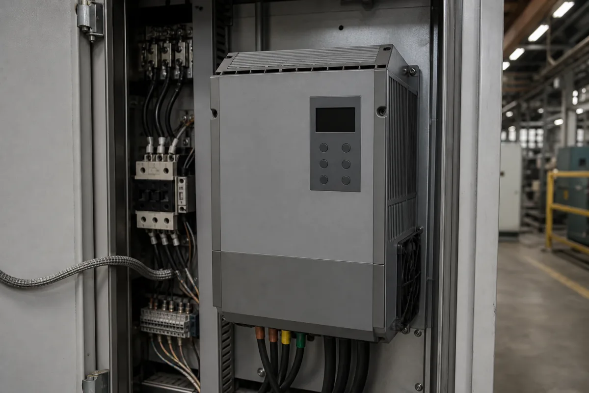
Variable frequency drive (VFD) in the control panel: input harmonics, chokes, heat loss and derating
Variable frequency drives on the supply side of a control panel · rectifier type and line harmonics, DC or AC chokes, IEEE 519 at the plant's supply point, watt loss and altitude derating
A variable frequency drive rectifies the mains, holds it on a DC bus and inverts it to a variable-frequency output for the motor. Seen from the panel builder's and the plant's side, the questions are about its input and its heat: how much harmonic current its rectifier draws from the supply, whether a DC or AC choke, a multi-pulse transformer or an active front end is needed to stay within the plant's harmonic limit, how many watts it releases inside the cabinet, and how much output current it loses at altitude or high ambient temperature.
Low-voltage variable frequency drives as installed in control panels and motor control centres, seen from the supply and the enclosure: rectifier type, line harmonics and their reduction, input chokes and filters, heat loss and current derating. Load types, affinity-law energy savings and motor-side protection against voltage spikes and bearing currents are covered on the Variable frequency drive page; conveyor speed controllers and drive packages are covered on the Conveyor motor speed controller page. Servo drives, DC drives, soft starters and medium-voltage drives are outside this page.
CNFX editorial research · Sources checked October 12, 2026 · 4 sources
Rectifier type and the harmonic current a drive draws from the supply
ABB's Technical guide No. 6 describes the 6-pulse diode bridge used in 3-phase AC drives as simple and cheap, but generating a high amount of low-order 5th, 7th and 11th harmonics, especially with small smoothing inductance. It summarises typical harmonic current components for each input design. [1]
Editorial calculation: the last column combines the six components ABB lists (5th, 7th, 11th, 13th, 17th and 19th) as a square root of the sum of squares; it leaves out higher orders, so it understates total distortion slightly. All percentages are of the fundamental current. [1]
ABB adds that if the major part of the load on a supply is converters with a 6-pulse rectifier, the supply transformer needs to be oversized and meeting harmonic standards may be difficult. [1]
Input design (ABB summary)
5th
7th
11th
13th
Relative manufacturing cost
Editorial calculation: root-sum-square of 5th–19th
250%, not significant if electrical braking is needed anyway [1]
≈ 6%
Give the supplier the transformer rating and impedance, the short-circuit level at the PCC (the point where the plant connects to the utility supply), the total drive load and other loads on that transformer, and the harmonic limit the plant or utility applies.
02
How much DC or AC inductance, and IEEE 519 at the plant's supply point
In ABB's guide, a large enough inductor in the AC input or the DC bus reduces a voltage-source drive's harmonics significantly. For the first 25 harmonics the theoretical THD minimum is 29 percent, practically reached at 100 mH divided by motor kW (1 mH for a 100 kW motor at 415 V, 50 Hz); about 25 mH divided by motor kW gives a THD of about 45 percent. [1]
Editorial calculation: for a 30 kW drive on the same 415 V, 50 Hz basis, 25 mH ÷ 30 ≈ 0.83 mH gives the practical point and 100 mH ÷ 30 ≈ 3.3 mH the near-minimum one. ABB notes the trend has been to shrink or omit the inductor as converters get smaller, so ask whether a choke is built in and its inductance. [1]
On IEEE 519, ABB explains that the standard sets limits for individual customers rather than individual equipment, tabulated by the ratio of available short-circuit current to maximum demand load current (Isc/IL) at the PCC, the point where the installation connects to the utility supply, and expressed as total demand distortion. It warns against applying the table to a single drive using that drive's own short-circuit ratio. [1] Editorial note: a supplier's statement that one drive "meets IEEE 519" therefore needs the plant's Isc/IL and load mix behind it.
03
Watt loss in the cabinet: interior unit loss against heatsink loss
Yaskawa's GA700 manual splits each drive's loss into interior unit loss and cooling fin (heatsink) loss, and lists an external heatsink installation method among its mounting options. [2]
Editorial calculation: for the 4060, the cooling fin carries 444 ÷ 601 ≈ 74% of the loss and the interior 26%; if the heatsink is mounted through the cabinet wall, the heat left inside is the 157 W interior figure rather than 601 W, before chokes and other panel components are added. Confirm with the supplier which loss figure applies to the mounting you choose.
The same manual lists heavy-duty ratings at higher carrier frequency: the 4060 is rated 45 A at 8 kHz with 515 W total loss, against 59.6 A at 2 kHz in normal duty. [2] Yaskawa also has the drive's ambient temperature and installation method (including side-by-side mounting in the panel) set by parameters L8-12 and L8-35, with output current derated to a curve for each method. [4]
Yaskawa specifies installation at 1,000 m or lower, with output current derated by 1% for each 100 m between 1,000 and 4,000 m. Rated voltage need not be derated up to 2,000 m, or between 2,000 and 4,000 m if the supply neutral is grounded. [3]
Editorial calculation: at 2,500 m the derating is (2,500 − 1,000) ÷ 100 = 15%, so a drive rated 59.6 A would be good for about 0.85 × 59.6 ≈ 50.7 A, before any temperature or mounting derating is applied. [3][2] State the site altitude and the maximum air temperature inside the panel in the enquiry so that both deratings are applied to the drive size quoted.
05
Send the supply, panel and site data with the motor list
Paste it into your enquiry below or into an email to a maker, then replace every bracket.
Motors: [kW; voltage; current; duty: normal or heavy]
Supply: [transformer kVA and impedance; short-circuit level at PCC; other loads]
Harmonic limit: [IEEE 519 TDD at PCC; utility or site rule]
Input design: [6-pulse with built-in choke; external AC or DC choke; 12/18/24-pulse; active front end]
Panel: [enclosure size; cooling; heatsink through wall or inside]
Site: [altitude; maximum ambient and panel temperature]
Carrier frequency: [kHz needed for noise]
2 companies list this product among what they make. Company figures are quoted from each
company's own website; every card states where the relationship came from.
Anyhertz Drive (Shenzhen) Co., Ltd.
Manufacturing site to be confirmed for the order
Lists low-voltage vector-control VFDs (FST-650L), elevator VFDs from 3.7 to 37 kW, and FST input and FSTL output filters rated 5 A to 1,600 A for 220/380/440 V drives.
Explore company information and manufacturing capabilities, then discuss the scope of your project with a relevant supplier.
Share this page
Compiled and source-reviewed by the CNFX editorial team.
Each manufacturer above links to the page on that company's own website where the product is listed, with the date we checked it. How we source and review
· Page last updated 13 October 2026
Buyer questions
How much does a choke reduce VFD harmonics?
ABB's summary lists a 6-pulse drive at 63% 5th and 54% 7th harmonic current without an inductor, and 30% and 12% with an AC or DC choke, at about 120% of the manufacturing cost. [1]
Does one VFD have to meet IEEE 519 on its own?
ABB explains that IEEE 519 limits apply to a customer's installation at its supply point (PCC), by its Isc/IL ratio, not to individual equipment. [1]
How much must a VFD be derated at high altitude?
Yaskawa's GA700 manual derates output current by 1% per 100 m between 1,000 and 4,000 m. [3]
Sources and what still needs a direct check
Sources checked 2026-10-12. ABB's Technical guide No. 6 is a drive maker's engineering guide to harmonics and IEEE 519; Yaskawa's GA700 technical manual pages give one drive family's watt loss and derating rules. Other drives differ, so ask for the same data for the model quoted.