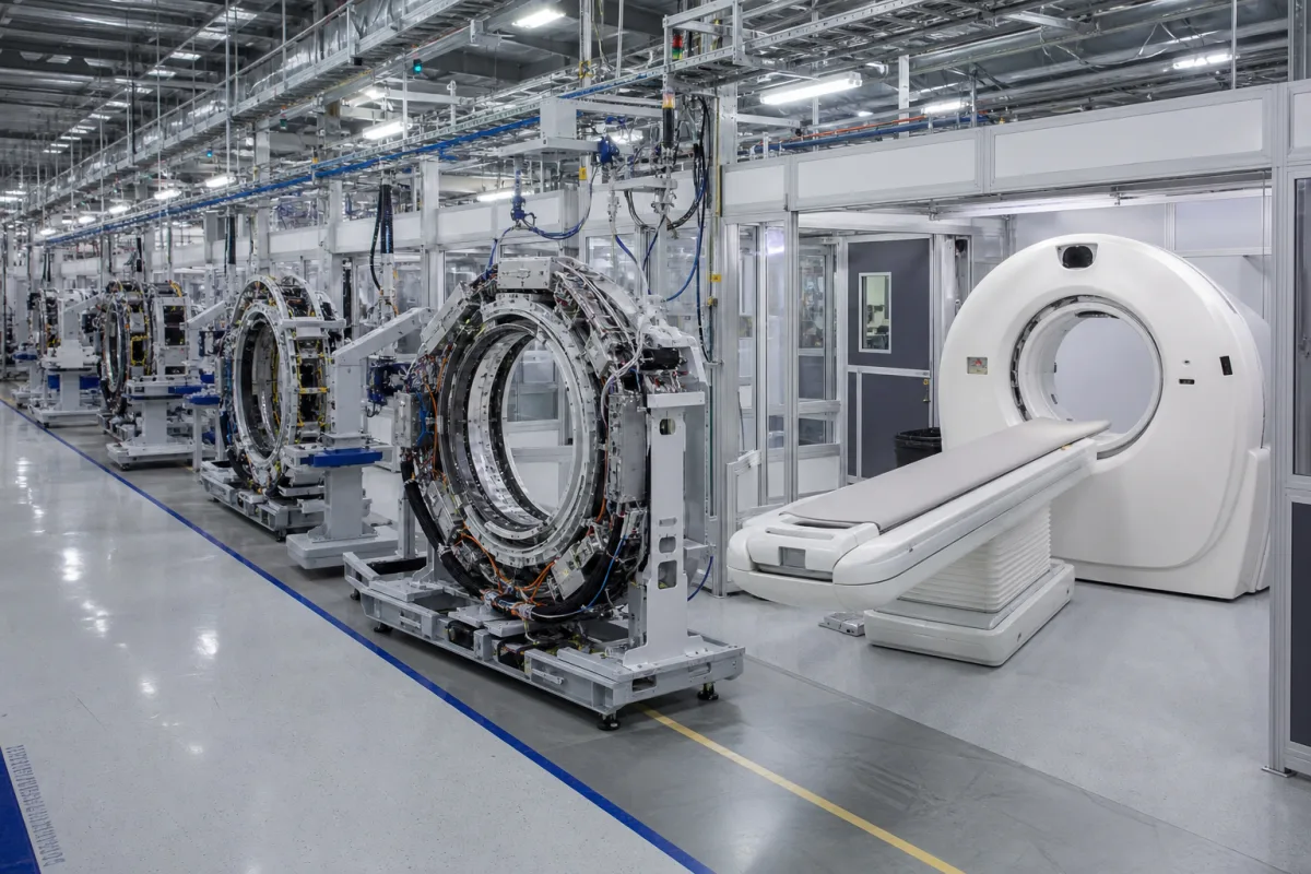
The Integrated Medical Imaging System Production Line is an automated industrial system for manufacturing key components used in medical imaging equipment, such as X-ray generators, detectors, and imaging plates. It coordinates multiple specialized modules, including precision assembly stations, vacuum processing chambers, and quality verification systems, to produce electromedical components at high volume while maintaining strict medical device quality standards through automated process control and inline testing. The system operates through a coordinated sequence of automated stations where raw materials and subcomponents are processed, assembled, and tested under controlled environmental conditions. It is designed for manufacturers of irradiation, electromedical, and electrotherapeutic equipment. The production line integrates stations for precision assembly, vacuum processing, and quality verification, with automated process control and inline testing to ensure consistent output. It handles materials such as stainless steel 316L, medical-grade plastics, copper alloys, and ceramic insulators. Key parameters include a production cycle time of 120–180 seconds, a system footprint of 25–40 square meters, power consumption of 15–25 kW, vacuum levels of 0.1–1.0 mbar, temperature control range of 20–30 °C, operating pressure of 1.0–1.6 MPa, positioning accuracy of ±0.02 mm (per ISO 230-2), electrical supply of 380–480 V AC (per IEC 60038), operating humidity of 45–65% RH, ingress protection of IP54–IP65 (per IEC 60529), material grade 316L (per ASTM A240), and machine weight of 8000–12000 kg. These values are reference ranges and must be verified for the specific model and application. The system is intended for integration into existing manufacturing facilities, with interfaces for power, compressed air, and data communication. Verification questions should address actual performance under load, compliance with applicable standards, and validation of process parameters. Maintenance signals include deviations in cycle time, positioning accuracy, or vacuum integrity. Failure boundaries are defined by the system's operational limits, such as maximum power, pressure, and temperature ranges.
The system operates through a coordinated sequence of automated stations. Raw materials and subcomponents are fed into precision assembly stations where robotic arms align and join parts with high accuracy. Assembled units then pass through vacuum processing chambers where controlled pressure and temperature conditions are applied for processes like sealing or coating. Inline quality verification systems inspect each component using sensors and automated tests, ensuring they meet specifications. The entire sequence is managed by a central control system that monitors parameters and adjusts operations in real time to maintain consistency and quality.