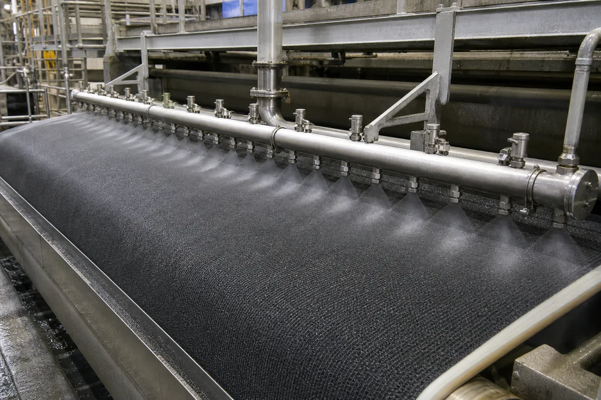
Spray manifold for felt conditioning showers: the distribution pipe inside the shower, sized for internal velocity, stiffness and even nozzle flow, with clamp-on nozzle fittings and individually valved zones
The pipe body that feeds a felt-conditioning shower's nozzles · keeping recycled water moving fast enough inside it, sizing it so it does not sag, holding the nozzle-to-nozzle flow even, clamping nozzles onto it, and splitting it into valved zones
Whatever nozzles a paper machine shower carries, they are fed by a manifold: a pipe closed at one end, supplied at the other, with a row of tapped or clamped outlets along its length. The manifold decides whether filtered, recycled water reaches the last nozzle as cleanly and at the same pressure as the first, whether the pipe stays straight across the machine, and whether individual nozzles can be switched. Those are pipe-body questions, separate from the choice of nozzle type, pressure and oscillation for the felt.
Spray manifolds (shower pipe bodies and distribution headers) for press felt and fabric conditioning showers on paper, board and tissue machines: internal passage and inserts, pipe diameter and support, feed arrangement and pressure distribution along the pipe, nozzle mounting (tapped, welded or clamp-on), zoning with individual nozzle valves, and header materials. Choosing needle-jet, fan, flooding or chemical showers, nozzle orifices, pressures, overlap and oscillation for felt conditioning is covered on the Felt conditioning shower page; the press section as a whole on the Paper machine press section page; doctor showers on the Paper machine doctoring system page.
CNFX editorial research · Sources checked October 13, 2026 · 4 sources
Inside the pipe: at least 2.6 m/s at the first nozzle so recycled-water solids stay suspended, and a bore set by stiffness rather than flow
Albany International's patent US 4,919,336 starts from a problem with shower pipes fed with filtered or recycled water: nozzle orifices block in use even though the particles left in the water are small enough to pass through them. Its finding is that the problem can be overcome by decreasing the effective cross-section of the flow path inside the pipe, raising the water velocity so solids do not separate out. [1]
The patent claims a minimum liquid velocity of 8 ft/s (2.6 m/s) in the passageway, at least at the first nozzle, and prefers that the passage narrow along the pipe so that velocity is held to the closed end where the flow is smallest. It achieves this with a partition or insert inside an ordinary pipe; two partitions are one example. [1]
The pipe's own bore, the patent explains, is set by structure and manufacture: it must not bend under the weight of the water it carries, although unsupported at its outer end, and nozzles must be easy to install. Its example is a minimum internal diameter of 26.5 mm (typ.) for a 450 mm pipe. [1] Brushes inside the pipe and purgeable nozzles are the other remedies the patent mentions for blocked orifices. [1]
Editorial calculation: a full 26.5 mm bore needs π/4 × 0.0265² m² × 2.6 m/s = 1.43 L/s, or 86 L/min, to reach 2.6 m/s at the first nozzle. [1] That is about seven of BETE's SF31FC clamp-on nozzles at 40 psi (3.10 gpm, 11.7 L/min each); a pipe feeding fewer or smaller nozzles runs slower than the patent's minimum unless its passage is reduced. [2]
Give the pipe length and support points, the water source (fresh, clarified or recycled) and its filtration, the total flow, and whether an internal insert, brush or purge is wanted to keep the nozzles clear.
02
Even flow from first to last nozzle: why nozzle flow follows Q = K·P^0.48, and what a 10 % pressure loss along the pipe costs
BETE's catalogue gives each nozzle's flow as a K factor and a pressure exponent. For its SF clamp-on series, flow in gpm = K × psi^0.48: [2]
Editorial calculation: with an exponent of 0.48, a nozzle at the far end of a manifold that sees 10 % less pressure than the first delivers 0.9^0.48 = 0.951 of its flow, about 5 % less; at 20 % less pressure, about 10 % less. [2] The pressure lost along the pipe therefore has to stay small against the pressure across the nozzles. Editorial note: a narrowed passage of the kind Albany describes raises the internal velocity and with it the friction loss along the pipe, so the insert is a balance between keeping solids moving and keeping the last nozzle's pressure close to the first. [1]
Spraying Systems Co., which makes headers and manifolds for pulp and paper among other industries, configures them by header length, number of zones, nozzle type and nozzle spacing, and describes its 63600 sanitary manifold as having large-diameter passages with minimal pressure drop to keep flow consistent. Its 103990 standard header comes in 36 in or 48 in lengths with up to 23 nozzles at 2, 4, 6, 8 or 10 in spacing. [3]
Ask for the calculated pressure at the first and last nozzle at design flow, the nozzle K factor and exponent, and the feed position.
03
Fixing nozzles to the pipe and switching them: clamp-on adapters rated 35 to 150 psi, and a solenoid valve per nozzle
Clamp-on adapters let nozzles be added to a plain pipe without threading it. BETE's SF snap-in clamp-on nozzles are polypropylene with a 302 stainless clamp and EPDM seal (Viton optional), fitted through a 21/32 in hole drilled in the pipe, for 1, 1-1/4, 1-1/2 and 2 in pipe. [2]
Editorial note: the larger the pipe, the lower BETE rates a single clamp, so low-pressure flooding or lubrication showers suit clamp-on fittings while high-pressure cleaning showers call for welded or threaded outlets. [2]
James Ross Ltd's patent US 5,595,632 turns the manifold into zones: an oscillating conduit assembly inside a fixed housing carries water nozzles and air nozzles, each with its own remotely controlled solenoid valve, so that any combination of nozzles can be opened to clean a streak in one longitudinal zone of the felt or dryer fabric while the oscillation moves the nozzles across the distance between neighbours. [4]
The image above shows a stainless shower pipe of this type across a machine fabric, fed from a vertical drop pipe, with a row of threaded nozzle fittings producing fan sprays onto the fabric.
State the nozzle connection (tapped, welded boss, clamp-on), the operating pressure, the pipe material, and whether nozzles must be switched individually or in zones.
04
Manifold details to send
Paste it into your enquiry below or into an email to a maker, then replace every bracket.
Pipe: [length; diameter; material; support points]
Water: [source; filtration; total flow; pressure]
Inside: [internal insert or partitions; brush; purge]
Nozzles: [type; K factor; count; spacing; connection]
Zoning: [individual valves; zones; air and water]
Motion: [fixed or oscillating; housing]
Explore company information and manufacturing capabilities, then discuss the scope of your project with a relevant supplier.
Share this page
Compiled and source-reviewed by the CNFX editorial team.
Each manufacturer above links to the page on that company's own website where the product is listed, with the date we checked it. How we source and review
· Page last updated 13 October 2026
Buyer questions
Why do shower pipe nozzles block even with filtered water?
Albany International's patent US 4,919,336 attributes it to solids settling out of slow-moving water inside the pipe and keeps the internal velocity at 2.6 m/s or more at the first nozzle with a partition or insert. [1]
How much does nozzle flow change with pressure along a manifold?
BETE gives SF nozzle flow as K × psi^0.48, so a nozzle seeing 10 % less pressure delivers about 5 % less flow, by editorial calculation. [2]
Can nozzles on a felt shower be switched individually?
James Ross Ltd's patent US 5,595,632 fits a solenoid valve to each water and air nozzle so any combination can be opened to clean a streaked zone. [4]
Sources and what still needs a direct check
Sources checked 2026-10-13. Four sources from four publishers: Albany International's US patent 4,919,336 on shower pipe internal velocity and bore, BETE's spiral nozzle catalogue for clamp-on nozzle flow and pressure ratings, Spraying Systems Co.'s headers and manifolds page, and James Ross Ltd's US patent 5,595,632 on individually valved shower nozzles.