Editorial Technical Reference

Heating Chamber

This page explains how Heating Chamber is classified within Rubber and Plastic Product Manufacturing. Technical values and manufacturer relationships are research references; confirm the current specification and supplier evidence for each order.

Technical Definition & Core Assembly

The insulated enclosure within a silicone curing oven where controlled heating occurs to cure silicone materials.
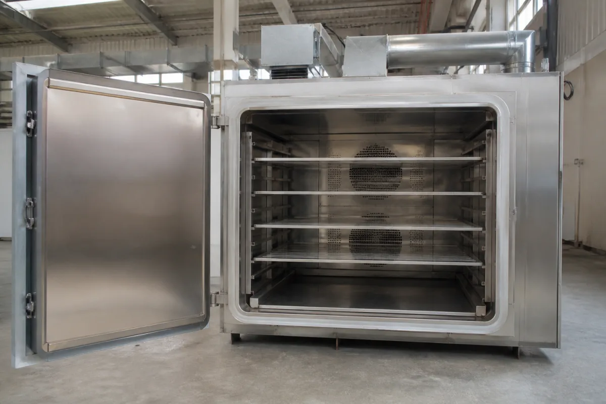
Representative product image. Confirm appearance and specifications with the manufacturer.

Product Specifications

Technical details and manufacturing context for Heating Chamber

Definition
The heating chamber is the core thermal processing zone of a silicone curing oven, designed to provide uniform, controlled heat distribution to silicone products or components placed within it. This enclosed space maintains precise temperature profiles essential for initiating and completing the silicone curing process, which involves cross-linking polymer chains to achieve desired material properties like elasticity, durability, and thermal resistance. The chamber is typically constructed from stainless steel (e.g., 304 or 316 grade) and insulated with materials such as ceramic fiber or mineral wool to minimize heat loss and ensure energy efficiency. Heating elements, such as nickel-chromium alloy wires or quartz tubes, are strategically positioned to convert electrical energy into thermal energy, which is then transferred to the silicone via convection, conduction, or radiation. Temperature sensors and controllers maintain the chamber at specific curing temperatures, typically ranging from 100°C to 300°C, for predetermined durations to ensure complete and consistent curing. The chamber's internal dimensions, maximum temperature, temperature uniformity, heating rate, power supply, heating power, insulation thickness, shell temperature, airflow velocity, leakage rate, and weight are critical parameters that must be verified for each specific model and application. For example, the internal dimensions may be custom-sized, with a standard reference of 1200 x 1200 x 1500 mm, and the maximum temperature is 350°C for continuous operation. Temperature uniformity is ±3°C at 200°C after stabilization, and the heating rate is 5–15°C/min from ambient to 200°C. The power supply is three-phase, 380 V AC ±10%, 50/60 Hz, with heating power ranging from 30–60 kW depending on chamber size. Insulation thickness is 100–150 mm, shell temperature is ≤45°C at max chamber temperature, airflow velocity is 1.5–3.0 m/s at the work zone, leakage rate is ≤0.5%/min at 1.5 kPa internal pressure, and weight is 800–1500 kg excluding external ducting. These values are directory references and must be confirmed with the legal manufacturer or supplier for the actual model.
Working Principle
The heating chamber operates by converting electrical energy into thermal energy through heating elements such as electric resistance heaters or gas burners, strategically positioned around the chamber. Heat is transferred to silicone materials via convection (air circulation), conduction (direct contact with heated surfaces), or radiation (infrared heating), depending on the oven design. Temperature sensors and controllers maintain the chamber at specific curing temperatures, typically ranging from 100°C to 300°C, for predetermined durations to ensure complete and consistent curing. The chamber's insulation minimizes heat loss, and airflow systems ensure uniform temperature distribution.
Common Materials
Stainless steel (e.g., 304 or 316 grade), Insulation materials (e.g., ceramic fiber, mineral wool), Heating elements (e.g., nickel-chromium alloy wires, quartz tubes)
Technical Parameters
ParameterTypical rangeNotes & selection driver
Internal Dimensions (W x D x H)1200 x 1200 x 1500 mmCustom sizes available
Maximum Temperature350 °CContinuous operation
Temperature Uniformity±3 °CAt 200°C after stabilization
Heating Rate5–15 °C/minFrom ambient to 200°C
Power Supply380 ±10% V ACThree-phase, 50/60 Hz
Heating Power30–60 kWDepending on chamber size
Insulation Thickness100–150 mmCeramic fiber or rock wool
Shell Temperature≤45 °CAt max chamber temperature
Airflow Velocity1.5–3.0 m/sAt work zone
Leakage Rate≤0.5 %/minAt 1.5 kPa internal pressure
Weight800–1500 kgExcluding external ducting

Ranges are indicative industry figures for RFQ preparation, not a supplier commitment. Confirm every value and standard with the legal manufacturer before ordering.

Components / BOM
  • Chamber Body
    The chamber shell itself: encloses the process volume and carries the operating pressure and temperature.
  • Heating Elements Part
    Generate heat through electrical resistance or combustion to raise the chamber temperature.
    Material: Nickel-chromium alloy, quartz, or ceramic
  • Insulation Layer Part
    Minimize heat loss to improve energy efficiency and maintain stable internal temperatures.
    Material: Ceramic fiber, mineral wool, or refractory bricks
  • Air Circulation System
    Distribute heat evenly throughout the chamber via fans or blowers to ensure uniform curing.
    Material: Stainless steel (fans, ducts)
  • Temperature Sensors
    Monitor chamber temperature and provide feedback to the control system for precise regulation.
    Material: Thermocouples (e.g., K-type) or RTDs

Applied To / Applications

This component is essential for the following industrial systems and equipment:

Industrial Ecosystem & Supply Chain Structure

Complementary Systems
Downstream Applications
Specialized Tooling

Application Fit & Sizing Matrix

Operational Limits
pressure: Atmospheric to 0.5 bar positive pressure
other spec: Heating rate: 1-10°C/min, uniformity: ±3°C across chamber
temperature: Ambient to 300°C (typical), up to 400°C (max)
Media Compatibility
✓ Liquid silicone rubber (LSR) ✓ High-consistency rubber (HCR) ✓ Silicone adhesives/sealants
Unsuitable: Corrosive chemical environments (e.g., strong acids, chlorinated solvents)
Sizing Data Required
  • Maximum part dimensions (LxWxH)
  • Required production throughput (parts/hour)
  • Target cure temperature profile (ramp/soak times)

Reliability & Engineering Risk Analysis

Failure Mode & Root Cause
Thermal stress cracking
Cause: Rapid temperature cycling causing differential expansion/contraction in chamber materials (insulation, heating elements, seals)
Heating element degradation
Cause: Oxidation and embrittlement from prolonged high-temperature operation, leading to element failure or reduced heating efficiency
Maintenance Indicators
  • Uneven temperature distribution across chamber (visualized via thermal imaging or multiple thermocouple readings)
  • Abnormal energy consumption spikes or unusual electrical/combustion sounds during operation
Engineering Tips
  • Implement controlled ramp-up/cooldown procedures to minimize thermal shock and stress on chamber components
  • Establish regular infrared thermography inspections to detect hot spots, insulation degradation, and electrical issues before catastrophic failure

Indicative industry ranges for design and RFQ preparation. Confirm the exact figures and applicable standard with the manufacturer before specifying.

Compliance & Manufacturing Standards

Applicable Standards
ASTM E84 - Standard test method for surface burning characteristics CE Marking - Compliance with EU directives for machinery safety

Quoted from the published standard.

Manufacturing Precision
  • Temperature uniformity: +/-5°C across chamber
  • Door seal gap: ≤0.5mm when closed
Quality Inspection
  • Thermal cycling test - Verifies temperature stability and recovery
  • Leakage current test - Ensures electrical safety and insulation integrity

Manufacturers of Heating Chamber

Manufacturer profiles associated with Heating Chamber.

Sourcing Heating Chamber from China?
Tell us your specification and target quantity — we will match it against manufacturer records and come back with the factories that fit.
Request manufacturers We manufacture this

Manufacturer listings support early research and capability understanding. They are not certification, ranking, or transaction guarantees.

Technical documentation
Request current drawings, revision history, and a signed specification sheet.
Manufacturing capability
Verify equipment lists, process limits, capacity, and representative production evidence.
Inspection readiness
Confirm test methods, calibrated equipment, sampling plans, and traceable reports.
Supplier transparency
Check the legal entity, factory address, ownership, certifications, and direct contacts.

CNFX does not score or rank suppliers. Buyers must verify all claims and documents with the legal manufacturer before ordering.

Supply Chain Compatible Machinery & Devices

High-Precision Silicone Gasket

A precision-engineered sealing component manufactured from liquid silicone rubber (LSR) via injection molding.

Explore Specs →
Silicone Rubber

A synthetic elastomer composed of silicone polymers with exceptional temperature resistance, flexibility, and chemical stability.

Explore Specs →
Non-post Cured

A rubber or plastic processing machine that produces cured products without requiring a separate post-curing stage.

Explore Specs →
Fumed Silicone Rubber

A high-performance silicone rubber reinforced with fumed silica, offering enhanced mechanical strength and thermal stability.

Explore Specs →

Frequently Asked Questions

What materials are used in the heating chamber construction?

The chamber is typically made of stainless steel (e.g., 304 or 316 grade) for the interior, with insulation materials such as ceramic fiber or mineral wool. Heating elements are often nickel-chromium alloy wires or quartz tubes. These are reference materials; confirm exact grades with the supplier.

What is the maximum operating temperature of the heating chamber?

The maximum temperature is 350°C for continuous operation, as listed in the directory. However, typical curing temperatures range from 100°C to 300°C. Always verify the specific temperature rating for your model.

How is temperature uniformity maintained inside the chamber?

Temperature uniformity is maintained through a combination of heating element placement, airflow circulation, and insulation. The directory lists a uniformity of ±3°C at 200°C after stabilization. Actual performance depends on the design and must be verified.

What are the electrical requirements for the heating chamber?

The power supply is three-phase, 380 V AC ±10%, 50/60 Hz. Heating power ranges from 30–60 kW depending on chamber size. These are reference values; check the nameplate and technical documentation for your specific unit.

Data Basis

Editorial classification, named public sources where available, and source-reviewed manufacturer records.

Preliminary Technical Classification
This page supports structured research, RFQ preparation, and supplier evaluation. It does not replace buyer-led supplier qualification, standards review, or technical approval.
Buyer enquiry

Request manufacturing insight for Heating Chamber

Ask for use case, specification boundaries, supplier type, and RFQ preparation information for this product.

Where it goes
Straight to the CNFX editorial desk, and to the manufacturer if this product is linked to a claimed profile. Nothing is broadcast to a supplier list.
Your details stay here
We do not sell or rent enquiry data, and we do not add you to a mailing list. Used only to answer this request.
No commission, no middleman
CNFX is a directory. We take no cut of any order and never negotiate on a supplier's behalf.
What we don't claim
A listing is not an endorsement. Qualify every supplier and verify every figure yourself before ordering.

Your business information is used only to process this request.

Thank you! Your message has been sent. We'll respond within 1–3 business days.
Sorry, we couldn't send your message. Please try again, or email us at contact@cnfx.com.

Need to Manufacture Heating Chamber?

Compare manufacturer profiles with relevant product and process capability.

Previous Product
Spray Manipulator
Last Product
Get QuotesChat