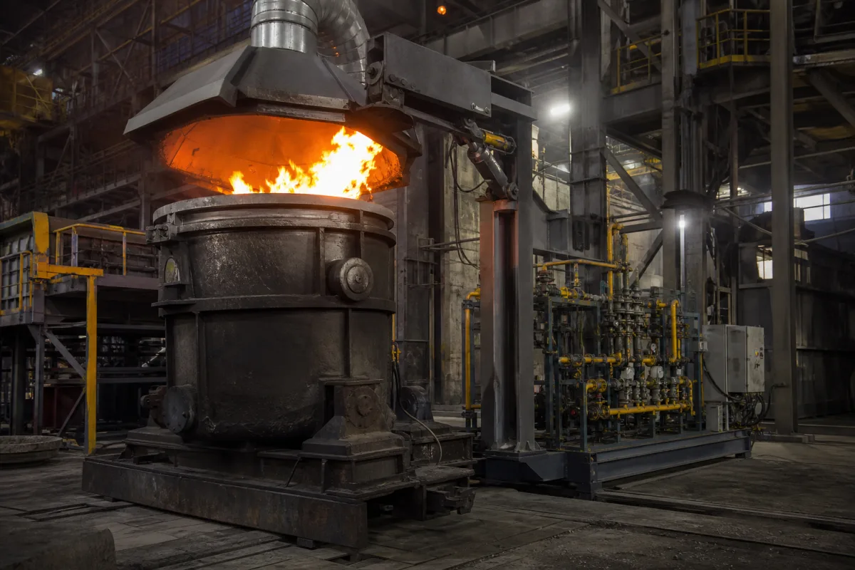
Ladle preheaters for steelworks and foundries · Vertical drying and horizontal preheating stands, lid-mounted burners of 1–5 MW, air-fuel versus oxy-fuel, preheat and soak stages, rim sealing and flue exhaust, recuperation, efficiency and fuel savings
A ladle preheating station is the fixed stand at which a refractory-lined ladle (or tundish or similar vessel) is covered by a lid carrying one or more burners and heated — to dry newly lined refractory, to bring the hot face up to temperature before it receives molten metal, and to keep it hot while it waits — so that the metal loses less heat and the furnace needs less superheat. Ask three things first: which ladles, sizes and duty cycle (drying, preheating, holding) the station must handle, which layout, burner rating, fuel and oxidant it will use, and how the lid seals, the flue gas is removed and the heating cycle is controlled.
Stationary ladle preheating and drying stations for steel and foundry ladles and tundishes: vertical and horizontal stands, lid and boom mechanisms, burners, combustion and oxygen trains, flues and controls. The ladles themselves (see refractory lined ladle), ladle furnaces for secondary metallurgy, ladle transfer cars and portable hand-held torches are outside this page except where compared.
CNFX editorial research · Sources checked October 11, 2026 · 5 sources
RWTH Aachen's industrial furnace department describes the ladle management system of an electric steelworks: after relining, the refractory must be dried and preheated before it holds molten steel; vertical ladle fires with the ladle standing upright dry newly lined refractory, while horizontal ladle fires preheat ladles with a lid in which the gas burner is integrated. The burners work in the 1–5 MW range and, in RWTH's words, "are usually operated with natural gas-air mixtures", with oxy-fuel systems used for higher efficiency and lower exhaust losses, and ladles are preheated to over 1,000 °C, which reduces heat loss from the melt, lowers the superheat needed in the arc furnace and shortens tap-to-tap time. [1]
US4718643A (American Combustion) describes ladles as preheated before use, kept hot while idle and heated when drying new or repaired linings, and splits heating into preheating the hot face to temperature and then soaking heat into the lining at that temperature; it gives an example control process to 2,100 °F with an auxiliary set point near 1,950 °F, and notes that some refractories need 50% more stored heat, about 30,000 Btu/ft², at 2,100 °F. [5]
Editorial calculation: 2,100 °F ≈ 1,149 °C and 1,950 °F ≈ 1,066 °C; 30,000 Btu/ft² ≈ 341 MJ per m² of lining. [5]
Give the supplier the ladle (or tundish) types, capacities, inside dimensions and rim condition, refractory types and their drying and heating curves, required hot-face temperature and time, number of ladles in circulation and the schedule, and whether stations are for drying, preheating, holding or all three.
02
Choose the burner, fuel and oxidant
A Chulalongkorn University thesis tested an 18 t steel ladle with an oil-fired air burner and a gas-fired oxy burner. For a cold ladle, flue and other losses were 59% with the air burner and 31% with the oxy burner, giving efficiencies of 34% and 57%; for a hot ladle, efficiency was 16% and 30%. Against the air burner, the oxy burner saved 41% (automatic mode) to 50% (high-fire mode) of energy on a cold ladle and 56–58% on a hot ladle, and cut preheating time by about 40%. [2]
Air Products states for its oxy-fuel ladle preheating systems that "Fuel savings on the order of 60-65% are routinely achieved due to the significant reduction of hot exhaust gas volumes as compared to air-fuel preheaters", and that the best choice depends on the existing preheater's operating parameters, fuel costs and production schedule. US4718643A combines oxygen with recuperatively preheated combustion air, using controlled oxygen to raise heat input in the initial preheat and to keep efficiency high in the soak, and controlling the air-to-oxygen ratio to reduce the nitrogen ballast with process temperature. [3][5]
Editorial note: the 60–65% figure is a supplier statement and the 41–58% figures are from one ladle with different fuels in each burner; ask for a guarantee based on your ladle, fuel and cycle. [3][2]
Specify fuel (natural gas, other gas, oil, hydrogen blends), oxidant (air, enriched air, oxygen), burner rating and turndown, oxygen supply and purity, combustion air preheat, flame safeguard and valve train, and the energy and time guarantee for your ladle and cycle.
03
Plan the lid, seal, exhaust and controls
US4014532A describes a concave refractory-lined cover with an axial burner projecting flame onto the lining (or, for large ladles, burners firing tangentially for uniform heating), flues in the cover to exhaust fumes while the cover sits tightly on the ladle mouth, and a fluid-operated boom that lowers the cover onto the ladle, lifts it and swings it aside; it was devised because earlier covers held clear of the mouth sent fumes and spatter towards workers. [4]
US4718643A identifies three energy losses at ladle stations — hot flue gas with poor fuel-air control, cold air infiltrating the gap between rim and lid, and radiation through that gap — and describes a lid with a partly open refractory ring that docks around rim protrusions from solidified metal and slag, a burner firing through the lid, and a water-cooled flue at the lid opening that draws off combustion products and infiltrated air. [5]
State the lid and boom or tilting mechanism, sealing method against your rim condition, flue and fume extraction, temperature measurement (lining, flue), the heating-cycle control and interlocks, and how the station links to the ladle tracking system.
04
Swing-boom lid, burner, flue, recuperator and upright or horizontal stand
The recuperator and the preheat-and-soak controls both come from US4718643A, which names hot flue gas, cold air drawn in at the rim gap and radiation through that gap as the losses a station has to recover or stop. [5]
Part
Role
Fix in the order
Lid (cover)
Refractory-lined; carries the burner and seals on the ladle. [4][1]
Preheat and soak cycle; fuel, air and oxygen ratio. [5]
Set points, sensors, logs.
Stand
Holds the ladle upright for drying or horizontal for preheating. [1]
Layout, ladle sizes.
05
Ladle size, burner arrangement, hot-face temperature and time to temperature for a preheater quotation
The time-to-temperature and flue-loss figures come from the single 18 t ladle tested at Chulalongkorn University, so ask for values measured on your own ladle sizes; thermocouple type, turndown, fuel pressure and combustion air have no published value here. [2]
Explore company information and manufacturing capabilities, then discuss the scope of your project with a relevant supplier.
Share this page
Compiled and source-reviewed by the CNFX editorial team.
Each manufacturer above links to the page on that company's own website where the product is listed, with the date we checked it. How we source and review
· Page last updated 13 October 2026
Buyer questions
How hot are steel ladles preheated?
RWTH Aachen describes transport ladles preheated to over 1,000 °C; one patent example heats to 2,100 °F. [1][5]
How much energy does oxy-fuel ladle preheating save?
One 18 t ladle study measured 41–58% less energy and 40% shorter preheating than an air burner. [2]
Why does a ladle preheater lid need flues?
So the lid can sit tightly on the ladle while fumes and spatter are exhausted away from workers. [4]
What is the difference between vertical and horizontal ladle stands?
Vertical stands dry newly lined refractory; horizontal stands preheat ladles under a burner lid. [1]
Sources and what still needs a direct check
Sources checked 2026-10-11. RWTH's project page and the Chulalongkorn thesis are university sources; the Air Products page is a supplier statement; the patents describe designs, not current products. Values for your station must come from the supplier offered.