Editorial Technical Reference

Gas Control System

This page explains how Gas Control System is classified within Basic Metal Manufacturing. Technical values and manufacturer relationships are research references; confirm the current specification and supplier evidence for each order.

Technical Definition & Core Assembly

A system that regulates and controls the flow, pressure, and composition of gases used in molten metal degassing processes.
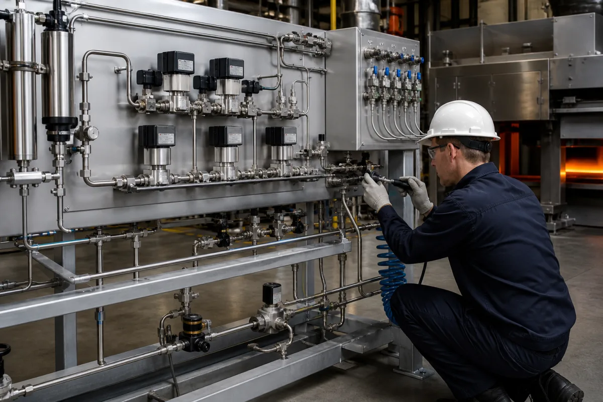
Gas Control System in a manufacturing environment
Representative product image. Confirm appearance and specifications with the manufacturer.

Product Specifications

Technical details and manufacturing context for Gas Control System

Definition
The Gas Control System is a critical component of the Molten Metal Degassing System responsible for precisely managing the injection of inert or reactive gases (such as argon or nitrogen) into molten metal. It controls gas flow rates, pressure, and distribution to facilitate the removal of dissolved hydrogen and non-metallic inclusions, ensuring consistent degassing efficiency and final metal quality. The system typically consists of pressure regulators, flow meters/controllers, valves, and piping. It receives gas from a supply source, regulates it to the required pressure, measures and controls the volumetric flow rate, and delivers it through injectors (like rotary degassers or lances) into the molten metal bath. Control may be manual or automated via PLC systems. Typical parameters include a maximum flow rate of 50–500 L/min, operating pressure of 2–10 bar, and compatibility with argon, nitrogen, and optionally chlorine. The system supports 1–4 injection points and uses pneumatic or electric actuated valves. Flow meter accuracy is ±0.5–1.0% of reading per ISO 5167, and pressure regulator accuracy is ±0.5–1.0% of set point. Response time is 1–5 seconds. Materials of construction include 316L stainless steel, PTFE, EPDM, and brass (for non-corrosive gases), with connection sizes of 1/4–1 inch per ANSI B1.20.1. Operating temperature range is -10 to +60 °C, with continuous duty cycle and a service life of 10–15 years. Power supply is 230 VAC, 50 Hz or 24 VDC, with control interfaces such as 4–20 mA, Modbus RTU, or Profibus DP. Ingress protection is IP54 (dry areas) or IP65 (washdown). Standards referenced include ISO 5167, ANSI B1.20.1, IEC 60529, IEC 61158, IEC 60038, ASTM A312, and ASTM D2000. Verify model-specific values and standards with the legal manufacturer or supplier.
Working Principle
The system receives gas from a supply source, typically at 2–10 bar. Pressure regulators reduce the pressure to the required injection level (1–3 bar). Flow meters/controllers measure and adjust the volumetric flow rate within the range of 50–500 L/min. Valves (pneumatic or electric) modulate the flow to each injection point. The gas is delivered through injectors such as rotary degassers or lances into the molten metal bath. Control can be manual or automated via PLC, using analog (4–20 mA) or digital (Modbus RTU, Profibus DP) interfaces. The system ensures precise gas distribution to facilitate removal of hydrogen and inclusions.
Common Materials
Stainless Steel (e.g., 316L), Brass, PTFE (Seals/Gaskets)
Technical Parameters
ParameterTypical rangeNotes & selection driver
Maximum Flow RateRequired50–500 L/minMaximum controllable gas flow rate
Operating PressureRequired2–10 bar2–10 — Inlet pressure from supply; outlet pressure regulated to 1–3 bar for injection.
Gas Type CompatibilityAr, N2, Cl2 (optional)Ar, N2, Cl2 (optional) — Materials must be compatible with dry chlorine if used; PTFE seals for Cl2.
Number of Injection Points1–4 points1–4 — Depends on ladle size and degassing method (lance vs. rotary).
Control Valve TypePneumatic or electric actuatedPneumatic or electric actuated — Electric for high accuracy; pneumatic for cost-sensitive.
Flow Meter Accuracy±0.5–1.0 % of reading±0.5–1.0 — For orifice plates; thermal mass meters have different standards.ISO 5167
Pressure Regulator Accuracy±0.5–1.0 % of set point±0.5–1.0 — Typical for high-precision regulators.
Response Time1–5 s1–5 — Time to reach 90% of set point after a step change.
Materials of Construction316L SS, PTFE, EPDM, brass (for non-corrosive gases)316L SS, PTFE, EPDM, brass (for non-corrosive gases) — 316L for wetted parts; PTFE for seals; brass for fittings if Cl2 not used.ASTM A312, ASTM D2000
Connection Size1/4–1 inch1/4–1 — NPT threads; size depends on flow rate.ANSI B1.20.1
Operating Temperature Range-10–+60 °C-10 to +60 — Ambient temperature for control cabinet; process gas temperature may be higher.
Duty CycleContinuousContinuous — Designed for 24/7 operation in steel plants.
Service Life10–15 years10–15 — With regular maintenance; seals may need replacement every 2–3 years.
Power Supply230 VAC, 50 Hz or 24 VDC230 VAC, 50 Hz or 24 VDC — For control system and actuators.IEC 60038
Control Interface4–20 mA, Modbus RTU, Profibus DP4–20 mA, Modbus RTU, Profibus DP — Analog and digital communication options.IEC 61158
Ingress ProtectionIP54 (dry areas), IP65 (washdown)IP54 (dry areas), IP65 (washdown) — For control cabinet and field devices.IEC 60529
Ambient temperature-10–+60 °C-10 to +60 °C — Outside this window: Below -10°C: seals may become brittle; above +60°C: electronics may overheat, causing control failure.
Inlet gas pressure2–10 bar2–10 bar — Outside this window: Below 2 bar: insufficient flow; above 10 bar: risk of overpressure damage to regulators and flow meters.
Gas purity≥99.99% for Ar, ≥99.9% for N2≥99.99% for Ar, ≥99.9% for N2 — Outside this window: Impurities can clog orifices and affect degassing efficiency; moisture can cause corrosion.
Flow rate50–500 L/min50–500 L/min — Outside this window: Below 50 L/min: inadequate gas coverage; above 500 L/min: may cause excessive turbulence and metal splashing.
Control accuracy±0.5–1.0% of set point±0.5–1.0% of set point — Outside this window: Worse accuracy leads to inconsistent degassing, affecting metal quality.

Ranges are indicative industry figures for RFQ preparation, not a supplier commitment. Confirm every value and standard with the legal manufacturer before ordering.

Components / BOM
  • Pressure Regulator
    Reduces and stabilizes inlet gas pressure to a set output pressure
    Material: Stainless Steel Body, Elastomer Diaphragm
  • Mass Flow Controller (MFC)
    Measures and controls the mass flow rate of gas with high precision
    Material: Stainless Steel, Electronics
  • Solenoid Valve
    Electrically actuated valve for on/off control of gas flow
    Material: Brass or Stainless Steel, PTFE Seals
  • Pressure Gauge
    Visual indicator of gas pressure in the system
    Material: Brass Case, Glass Lens
  • Injection Lance / Rotary Degasser
    The part that actually goes into the melt and releases the gas.
  • PLC Control Interface
    Takes the 4-20 mA or fieldbus commands and drives the regulators and valves.

Industry Taxonomies & Aliases

Commonly used trade names and technical identifiers for Gas Control System.

Applied To / Applications

This component is essential for the following industrial systems and equipment:

Industrial Ecosystem & Supply Chain Structure

Complementary Systems
Downstream Applications
Specialized Tooling

Application Fit & Sizing Matrix

What Decides the Award
  • What is the maximum required gas flow rate for your ladle size and degassing method?
  • What level of control accuracy is needed for your process (e.g., ±0.5% vs. ±1%)?
  • Which gases will be used (Ar, N2, Cl2) and what purity?
  • What is the existing control system interface (PLC brand, communication protocol)?
  • What is the ambient environment (temperature, dust, washdown) and required IP rating?
  • What is the acceptable response time for flow changes?
  • What is the budget and expected service life?
Failure Modes & Inspection
  • Leakage
    Check: Pressure decay test: pressurize system to 10 bar, isolate, and monitor pressure drop over 30 min; use soap solution for bubble test.
  • Flow measurement drift
    Check: Calibrate flow meter against a reference standard (e.g., primary standard) at least annually; compare readings at multiple set points.
  • Valve sticking
    Check: Cycle valve 100 times and check response time; inspect actuator for proper operation; clean or replace if necessary.
  • Pressure regulator instability
    Check: Check output pressure stability over 1 hour; adjust or replace regulator if fluctuation exceeds ±1% of set point.
  • Corrosion
    Check: Visual inspection for pitting or discoloration; use borescope for internal surfaces; replace wetted parts if corrosion is found.

Reliability & Engineering Risk Analysis

Failure Mode & Root Cause
Valve seat leakage
Cause: Wear from particulate contamination in gas stream, improper material selection for gas composition, or thermal cycling causing seat deformation
Actuator failure
Cause: Moisture ingress leading to electrical short circuits, mechanical binding from lack of lubrication, or control signal interference from electromagnetic sources
Maintenance Indicators
  • Audible hissing or whistling sounds indicating gas leakage
  • Erratic pressure readings or control response outside normal operating parameters
Engineering Tips
  • Implement regular gas quality monitoring and filtration to remove particulates and moisture before they reach control components
  • Establish predictive maintenance program using vibration analysis for rotating components and thermal imaging for electrical connections to detect early degradation

Indicative industry ranges for design and RFQ preparation. Confirm the exact figures and applicable standard with the manufacturer before specifying.

Compliance & Manufacturing Standards

Applicable Standards
ISO 13849-1: Safety of machinery - Safety-related parts of control systems ANSI/ISA 84.00.01: Functional safety - Safety instrumented systems for the process industry sector DIN EN 50156-1: Electrical equipment for furnaces and ancillary equipment - Requirements for application design and erection

Quoted from the published standard.

Manufacturing Precision
  • Pressure rating: +/- 1% of full scale
  • Leakage rate: < 0.5% of maximum flow capacity
Quality Inspection
  • Pressure decay leak test
  • Functional safety verification test

Manufacturers of Gas Control System

1 company lists this product among what they make. Company figures are quoted from each company's own website; every card states where the relationship came from.

Fitok Group
Beijing, CN
Listed on the company's own website · profile compiled by CNFX from public sources
Listed there as: “Gas Control Systems”
View source page ↗ fitokgroup.com · checked 2026-08-31

Manufacturer listings support early research and capability understanding. They are not certification, ranking, or transaction guarantees.

Share this page
Technical documentation
Request current drawings, revision history, and a signed specification sheet.
Manufacturing capability
Verify equipment lists, process limits, capacity, and representative production evidence.
Inspection readiness
Confirm test methods, calibrated equipment, sampling plans, and traceable reports.
Supplier transparency
Check the legal entity, factory address, ownership, certifications, and direct contacts.

CNFX does not score or rank suppliers. Buyers must verify all claims and documents with the legal manufacturer before ordering.

Supply Chain Compatible Machinery & Devices

Electroslag Remelting Furnace

An industrial furnace used in basic metal manufacturing for secondary refining of alloys through the electroslag remelting (ESR) process.

Explore Specs →
Molten Metal Temperature Measurement System

Automated system for continuous temperature monitoring of molten metals during processing.

Explore Specs →
Molten Metal Degassing System

The Molten Metal Degassing System is an industrial system used in basic metal manufacturing to remove dissolved hydrogen, oxygen, and nitrogen from molten aluminum, steel, and other non-ferrous metals.

Explore Specs →
Molten Metal Level Control System

Automated system for precise molten metal level monitoring and control in furnaces and vessels.

Explore Specs →

Frequently Asked Questions

What gases can the Gas Control System handle?

The system is compatible with argon (Ar), nitrogen (N2), and optionally chlorine (Cl2). For chlorine, materials must be compatible, and PTFE seals are recommended. Verify gas purity requirements: ≥99.99% for Ar and ≥99.9% for N2.

What is the typical flow rate range?

The maximum controllable flow rate is typically 50–500 L/min, depending on ladle size and degassing method. Lower flows may be inadequate for gas coverage, while higher flows can cause excessive turbulence and splashing.

What control interfaces are available?

The system can be controlled via analog signals (4–20 mA) or digital protocols such as Modbus RTU and Profibus DP, per IEC 61158. This allows integration with PLC-based automation systems.

What maintenance is required?

Regular maintenance is needed to ensure accuracy and longevity. Seals may require replacement every 2–3 years. The service life is typically 10–15 years with proper maintenance. Check for leaks, calibrate flow meters, and inspect valves periodically.

Data Basis

Editorial classification, named public sources where available, and source-reviewed manufacturer records.

Preliminary Technical Classification
This page supports structured research, RFQ preparation, and supplier evaluation. It does not replace buyer-led supplier qualification, standards review, or technical approval.
Buyer enquiry

Request manufacturing insight for Gas Control System

Ask for use case, specification boundaries, supplier type, and RFQ preparation information for this product.

Where it goes
Straight to the CNFX editorial desk, and to the manufacturer if this product is linked to a claimed profile. Nothing is broadcast to a supplier list.
Your details stay here
We do not sell or rent enquiry data, and we do not add you to a mailing list. Used only to answer this request.
No commission, no middleman
CNFX is a directory. We take no cut of any order and never negotiate on a supplier's behalf.
What we don't claim
A listing is not an endorsement. Qualify every supplier and verify every figure yourself before ordering.

Your business information is used only to process this request.

Thank you! Your message has been sent. We'll respond within 1–3 business days.
Sorry, we couldn't send your message. Please try again, or email us at [email protected].

Need to Manufacture Gas Control System?

Compare manufacturer profiles with relevant product and process capability.

Previous Product
Forging-Grade Titanium Alloy Bar Stock
Next Product
Hearth
Get QuotesChat