Editorial Technical Reference

Lance Body/Tube

This page explains how Lance Body/Tube is classified within Basic Metal Manufacturing. Technical values and manufacturer relationships are research references; confirm the current specification and supplier evidence for each order.

Technical Definition & Core Assembly

The main structural component of an oxygen lance that houses and protects the oxygen delivery mechanism.
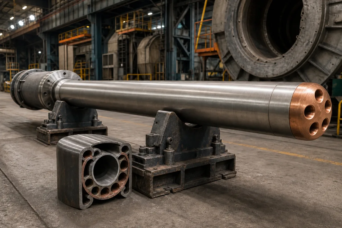
Representative product image. Confirm appearance and specifications with the manufacturer.

Product Specifications

Technical details and manufacturing context for Lance Body/Tube

Definition
The lance body or tube is the primary structural element of an oxygen lance system used in steelmaking processes. It serves as the protective housing for the internal oxygen delivery channels and cooling systems, providing mechanical strength and thermal resistance during operation. This component connects to the lance head at one end and the supply system at the other, forming the critical conduit through which oxygen is delivered to molten metal in basic oxygen furnaces or electric arc furnaces. The lance body/tube is typically manufactured from low carbon steel, stainless steel, or copper alloys, depending on the specific requirements of the application. Key parameters include outer diameter (89–219 mm), wall thickness (6–20 mm), length (3000–12000 mm), operating pressure (1.0–1.6 MPa), operating temperature (-20–200 °C), cooling water flow rate (30–80 m³/h), cooling water pressure drop (0.2–0.5 MPa), material grade (e.g., 20G per GB/T 5310), surface roughness (≤3.2 μm Ra), straightness tolerance (≤1.5 mm/m), and weight (150–800 kg). These values are reference ranges and must be confirmed for the specific model and application. The lance body/tube must meet relevant standards such as GB/T 8162 for dimensions, but compliance must be verified with the manufacturer. Proper selection requires consideration of furnace geometry, lance tip size, and operating conditions. Regular inspection for wear, thermal damage, and blockage is essential to maintain safe and efficient operation.
Working Principle
The lance body/tube functions as a pressure vessel and thermal barrier that withstands extreme temperatures (up to 1600-1700°C) and mechanical stresses during steelmaking operations. It maintains structural integrity while allowing oxygen to flow through internal channels to the lance tip, where it reacts with molten metal. Cooling water typically circulates through annular spaces within the tube to prevent thermal damage. The design ensures that the cooling water flow rate and pressure drop remain within specified ranges to avoid boiling and ensure effective heat removal. The outer diameter and wall thickness are chosen to match the lance tip and furnace port, while the length is customized to the furnace geometry. The material grade, such as 20G carbon steel, is selected for high-temperature service. The surface roughness and straightness tolerance are controlled to minimize flow resistance and ensure proper alignment. During operation, the lance body/tube must maintain its integrity under thermal and mechanical stress; any significant deviation in cooling water pressure drop may indicate blockage or scaling, requiring maintenance.
Common Materials
Low carbon steel, Stainless steel, Copper alloys
Technical Parameters
ParameterTypical rangeNotes & selection driver
Outer Diameter89–219 mmMatches lance tip and furnace port sizeGB/T 8162
Wall Thickness6–20 mmThicker for higher pressure or wearGB/T 8162
Length3000–12000 mmCustomized to furnace geometry
Operating Pressure1.0–1.6 MPa
Operating Temperature-20–200 °CCooling water must prevent boiling
Cooling Water Flow Rate30–80 m³/hEnsures heat removal at high lance rates
Cooling Water Pressure Drop0.2–0.5 MPaHigher drop indicates blockage or scaling
Material Grade20GCarbon steel for high-temp serviceGB/T 5310
Surface Roughness≤3.2 μm RaSmooth bore reduces flow resistanceISO 1302
Straightness Tolerance≤1.5 mm/mEnsures proper lance alignmentISO 1101
Weight150–800 kgDepends on length and wall thickness

Ranges are indicative industry figures for RFQ preparation, not a supplier commitment. Confirm every value and standard with the legal manufacturer before ordering.

Components / BOM
  • Outer Shell Part
    Provides structural integrity and houses internal components
    Material: Low carbon steel
  • Oxygen Channel Part
    Conduit for high-pressure oxygen delivery to the lance tip
    Material: Stainless steel
  • Cooling Water Jacket Part
    Annular space for water circulation to dissipate heat
    Material: Copper alloy or steel
  • Connection Flange Part
    Interface for connecting to oxygen supply and cooling systems
    Material: Carbon steel

Industry Taxonomies & Aliases

Commonly used trade names and technical identifiers for Lance Body/Tube.

Applied To / Applications

This component is essential for the following industrial systems and equipment:

Industrial Ecosystem & Supply Chain Structure

Complementary Systems
Downstream Applications
Specialized Tooling

Application Fit & Sizing Matrix

Operational Limits
pressure: Maximum operating pressure: 15 bar (217.5 psi), burst pressure: 45 bar (652.5 psi)
flow rate: Oxygen flow capacity: 50-500 Nm³/h (1765-17650 SCFH) depending on diameter
temperature: Up to 1800°C (3272°F) for short-term exposure, continuous operation up to 1200°C (2192°F)
slurry concentration: Not applicable - designed for pure oxygen or oxygen-enriched gas delivery
Media Compatibility
✓ Basic oxygen furnace (BOF) steelmaking ✓ Electric arc furnace (EAF) steelmaking ✓ Copper smelting/converting processes
Unsuitable: Chlorine or fluorine-containing atmospheres (causes severe corrosion)
Sizing Data Required
  • Required oxygen flow rate (Nm³/h)
  • Lance insertion depth into molten metal bath (meters)
  • Available lance holder connection diameter (mm)

Reliability & Engineering Risk Analysis

Failure Mode & Root Cause
Abrasive erosion
Cause: Prolonged exposure to high-velocity particulate-laden fluids, leading to material loss and thinning of the lance body/tube walls, especially at bends or constrictions.
Thermal fatigue cracking
Cause: Cyclic thermal stresses from rapid heating and cooling cycles, often due to intermittent operation or process fluctuations, causing cracks at weld joints or material transitions.
Maintenance Indicators
  • Visible thinning or localized wear spots on the lance body, often indicated by discoloration or reduced wall thickness.
  • Audible hissing or whistling sounds during operation, suggesting leaks or internal erosion compromising structural integrity.
Engineering Tips
  • Implement regular ultrasonic thickness testing at critical sections to monitor wall thinning and schedule proactive replacements before failure.
  • Optimize operating parameters to minimize thermal cycling, such as using gradual heating/cooling ramps and maintaining consistent process temperatures.

Indicative industry ranges for design and RFQ preparation. Confirm the exact figures and applicable standard with the manufacturer before specifying.

Compliance & Manufacturing Standards

Applicable Standards
ASTM A269/A269M - Standard Specification for Seamless and Welded Austenitic Stainless Steel Tubing EN 10204:2004 - Metallic products - Types of inspection documents

Quoted from the published standard.

Manufacturing Precision
  • Wall thickness: +/-0.1mm
  • Straightness: 0.5mm per meter length
Quality Inspection
  • Hydrostatic pressure test
  • Visual and dimensional inspection

Manufacturers of Lance Body/Tube

Manufacturer profiles associated with Lance Body/Tube.

Sourcing Lance Body/Tube from China?
Tell us your specification and target quantity — we will match it against manufacturer records and come back with the factories that fit.
Request manufacturers We manufacture this

Manufacturer listings support early research and capability understanding. They are not certification, ranking, or transaction guarantees.

Technical documentation
Request current drawings, revision history, and a signed specification sheet.
Manufacturing capability
Verify equipment lists, process limits, capacity, and representative production evidence.
Inspection readiness
Confirm test methods, calibrated equipment, sampling plans, and traceable reports.
Supplier transparency
Check the legal entity, factory address, ownership, certifications, and direct contacts.

CNFX does not score or rank suppliers. Buyers must verify all claims and documents with the legal manufacturer before ordering.

Supply Chain Compatible Machinery & Devices

Continuous Casting Machine

Industrial machine for solidifying molten metal into continuous billets/blooms/slabs.

Explore Specs →
Vacuum Induction Melting Furnace

Industrial furnace for melting metals under vacuum using electromagnetic induction

Explore Specs →
Electroslag Remelting Furnace

An industrial furnace used in basic metal manufacturing for secondary refining of alloys through the electroslag remelting (ESR) process.

Explore Specs →
Molten Metal Temperature Measurement System

Automated system for continuous temperature monitoring of molten metals during processing.

Explore Specs →

Frequently Asked Questions

What is the function of the lance body/tube?

The lance body/tube is the main structural component of an oxygen lance system. It houses and protects the internal oxygen delivery channels and cooling systems, providing mechanical strength and thermal resistance during steelmaking operations.

What materials are commonly used for the lance body/tube?

Common materials include low carbon steel, stainless steel, and copper alloys. The specific material grade, such as 20G carbon steel, is selected based on the application's temperature and pressure requirements.

What are the typical dimensions of a lance body/tube?

Typical reference ranges are: outer diameter 89–219 mm, wall thickness 6–20 mm, and length 3000–12000 mm. These values must be confirmed for the specific model and furnace geometry.

How is the lance body/tube cooled during operation?

Cooling water circulates through annular spaces within the tube. The flow rate is typically 30–80 m³/h, and the pressure drop is 0.2–0.5 MPa. Proper cooling prevents thermal damage and ensures safe operation.

Data Basis

Editorial classification, named public sources where available, and source-reviewed manufacturer records.

Preliminary Technical Classification
This page supports structured research, RFQ preparation, and supplier evaluation. It does not replace buyer-led supplier qualification, standards review, or technical approval.
Buyer enquiry

Request manufacturing insight for Lance Body/Tube

Ask for use case, specification boundaries, supplier type, and RFQ preparation information for this product.

Where it goes
Straight to the CNFX editorial desk, and to the manufacturer if this product is linked to a claimed profile. Nothing is broadcast to a supplier list.
Your details stay here
We do not sell or rent enquiry data, and we do not add you to a mailing list. Used only to answer this request.
No commission, no middleman
CNFX is a directory. We take no cut of any order and never negotiate on a supplier's behalf.
What we don't claim
A listing is not an endorsement. Qualify every supplier and verify every figure yourself before ordering.

Your business information is used only to process this request.

Thank you! Your message has been sent. We'll respond within 1–3 business days.
Sorry, we couldn't send your message. Please try again, or email us at contact@cnfx.com.

Need to Manufacture Lance Body/Tube?

Compare manufacturer profiles with relevant product and process capability.

Previous Product
Work Rolls
Last Product
Get QuotesChat