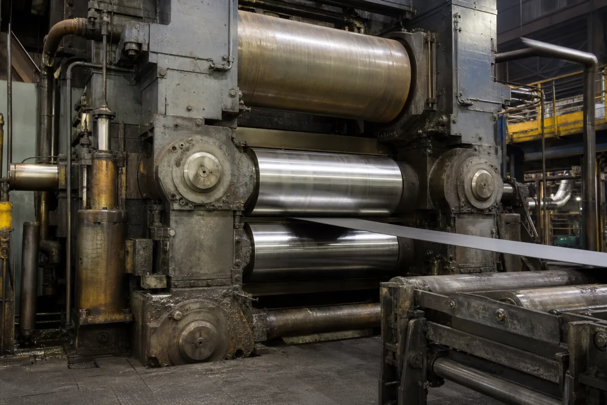
Single-stand reversing cold rolling stand: the four-high mill that reduces steel or copper-alloy strip coil to coil in repeated passes
Cold rolling · one four-high stand that rolls a coil back and forth between two reels until it reaches gauge: tonnage, width and gauge range, speed, and the flatness tools carried in the stand
In a reversing cold mill the coil is threaded through the stand, wound onto the far reel, and then run back the other way with the roll gap closed a little more, pass after pass, until it reaches the ordered gauge. What a buyer has to pin down is the tonnage, the width and gauge range, the speed, and which flatness and gauge controls are built into the stand.
Single-stand reversing cold rolling mills built around one four-high stand with tension reels on both sides, for steel and for copper and copper-alloy strip, including stands combined with skin-pass duty and the roll bending, roll shifting, roll cooling and gauge control equipment fitted to them. Hot two-high and four-high strip and plate stands are covered on the Heavy-duty rolling mill stand page, and hot reversing mills with coiler furnaces on the Steckel mill page; multi-stand hot finishing trains for aluminium on the Multi-stand hot tandem finishing mill for aluminium strip page. The stand housing alone is covered on the Rolling mill housing (mill stand frame) page, bearing chocks on the Roll chocks for four-row tapered roller bearings page, work and backup rolls on the Rolling mill work roll and Backup rolls pages, and the gap actuators on the Hydraulic screwdown cylinder of a rolling mill, Heavy-duty rolling mill hydraulic gap control system and Electromechanical screwdown mechanism pages.
CNFX editorial research · Sources checked October 13, 2026 · 4 sources
Tyasa's single four-high stand: 200,000 t a year of 0.3–1 mm steel strip, and the flatness tools that came with it
When Mexico's Talleres y Aceros (Tyasa) ordered a reversing cold mill from Primetals Technologies for its Ixtaczoquitlan mini-mill in 2016, Primetals described a single-stand, four-high mill able to roll 200,000 metric tons a year of high-strength and low-carbon steels, in thicknesses of 0.3 to 1 mm and widths of 900 to 1,650 mm. [1]
Primetals named the equipment that was to keep the strip flat: work roll bending, multizone cooling of the work rolls and continuous flatness measurement, combined with technology packages such as automatic flatness control. [1] The order covered the process equipment, the electrical and automation packages and supervision of installation and start-up. [1]
In the start-up release on the Mitsubishi Heavy Industries news site, the mill rolled its first coil in January 2018 and the project was completed in 21 months. [2] The release describes the stand as designed for 200,000 metric tons a year of low-carbon and high-strength grades, suited in particular to small batches, and says its compact design minimises the length of out-of-tolerance strip thickness. [2]
Editorial calculation from the Tyasa figures: at 200,000 t a year, the stand averages about 548 t a day over 365 days; this is an average over the year, not an hourly rating, and the release gives no speed. [2]
State the steel grades and their entry strength, the entry and finished thickness, the width range, the coil weight, the annual tonnage and batch sizes, and the flatness and thickness tolerances the stand must hold; ask which flatness actuators and measurements are in the stand.
02
Three reversing four-high stands side by side: a steel stand, a combined rolling and skin-pass stand, and a precision copper-alloy stand
The published data for three single-stand reversing mills show how far the same arrangement is stretched in width, gauge and speed.
The Starcore stand does two jobs: a combined reversing and skin-pass mill, four-high with CVC roll shifting, in which the cylinder and bending blocks and the CVC shifting systems came from SMS Siemag's Hilchenbach works while the whole stand was pre-assembled by Esmech in India before erection. [3] The Tenova mill is listed as a 75 & 320 × 310 mm four-high reversing mill with automatic gauge control, contact thickness gauges and AC drives; editorial reading of that designation is a 75 mm work roll and 320 mm backup roll on a 310 mm face, which the source does not spell out. [4]
Editorial calculations: 1,200 m/min is 20 m/s at the Starcore stand; 300 m/min is 5 m/s at the copper-alloy stand. The thinnest strip of the three, 0.03 mm, is one tenth of Tyasa's 0.3 mm lower limit, on a strip at most 250 mm wide against 1,650 mm. [4][1][3]
Speed, finished gauge and width come as separate maxima in these releases; ask the stand supplier for the speed and reduction it reaches at your thinnest gauge and widest strip together, not each limit on its own.
03
Data a reversing cold stand supplier needs
Paste it into your enquiry below or into an email to a maker, then replace every bracket.
Material: [steel grades or copper alloys; entry strength; hot band or prior cold reduction]
Entry: [thickness range; width range; coil weight; coil inner and outer diameter]
Product: [finished thickness range; thickness and flatness tolerances; surface]
Output: [tonnes per year; batch size; skin-pass duty needed or not]
Stand: [four-high; roll bending; roll shifting; work roll cooling zones]
Control: [automatic gauge control; flatness measurement and control; thickness gauges]
Speed: [maximum rolling speed; threading speed]
Explore company information and manufacturing capabilities, then discuss the scope of your project with a relevant supplier.
Share this page
Compiled and source-reviewed by the CNFX editorial team.
Each manufacturer above links to the page on that company's own website where the product is listed, with the date we checked it. How we source and review
· Page last updated 13 October 2026
Buyer questions
What does a single-stand reversing cold mill roll?
Primetals' mill for Tyasa was described as a single four-high stand rolling 200,000 t a year of high-strength and low-carbon steel strip 0.3–1 mm thick and 900–1,650 mm wide. [1]
How fast can a reversing cold stand roll?
The SMS Siemag reversing and skin-pass mill at Starcore is reported at up to 1,200 m/min for strip up to 1,250 mm wide; a Tenova copper-alloy stand is reported at 300 m/min. [3][4]
Can one stand also skin-pass?
Starcore's combined reversing and skin-pass mill is reported with 200,000 t a year of cold rolled strip and 146,000 t a year of skin-passing capacity. [3]
How thin can a reversing four-high stand roll copper alloys?
Tenova I2S's stand for APO Uzbek Metallurgical Plant is reported to roll copper and copper-based alloys from 0.5 down to 0.03 mm, 100 to 250 mm wide. [4]
Sources and what still needs a direct check
Sources checked 2026-10-13. AIST news items report the Tyasa order (citing Primetals), the Starcore start-up and the Tenova copper-alloy mill; the Tyasa start-up release is on the news site of Mitsubishi Heavy Industries.