Editorial Technical Reference

Servo Control Valve

This page explains how Servo Control Valve is classified within Basic Metal Manufacturing. Technical values and manufacturer relationships are research references; confirm the current specification and supplier evidence for each order.

Technical Definition & Core Assembly

A precision hydraulic valve that regulates fluid flow and pressure in response to electrical control signals to achieve accurate positioning and force control.
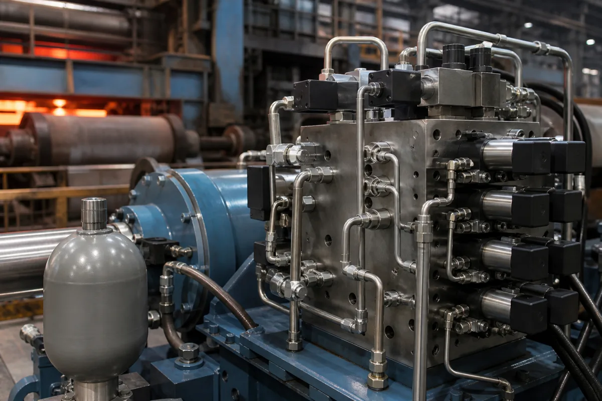
Representative product image. Confirm appearance and specifications with the manufacturer.

Product Specifications

Technical details and manufacturing context for Servo Control Valve

Definition
The Servo Control Valve is a critical component within the Heavy-Duty Rolling Mill Hydraulic Gap Control System. It precisely translates electronic commands from the system's controller into proportional hydraulic fluid flow and pressure, directly actuating the hydraulic cylinders that adjust the roll gap. This enables the mill to maintain exacting thickness tolerances and apply consistent rolling forces on metal slabs or strips. The valve operates on a closed-loop principle: a low-power electrical signal (e.g., from a servo amplifier) is converted by an internal torque motor or solenoid into a mechanical force, which moves a spool or flapper inside the valve body. This movement modulates the opening of hydraulic ports, controlling the rate and direction of high-pressure oil flow to the actuator. A feedback mechanism, often an LVDT, monitors spool position to ensure high accuracy and stability. Key parameters include rated flow (10–100 L/min at rated pressure drop), maximum operating pressure (21–35 MPa), hysteresis (≤0.5%), linearity (≤1.0%), step response time (10–50 ms), supply voltage (24 V DC ±10%), control signal (4–20 mA), operating temperature (-20 to 60 °C), ingress protection (IP65–IP67), body material (stainless steel 304–316), and weight (5–15 kg). These values are reference ranges per ISO 10770-1 and IEC 60381-1; actual specifications must be confirmed with the legal manufacturer for the specific model and application. The valve is designed for use in basic metal manufacturing environments, with materials including alloy steel for the body and spool, stainless steel for internal components, and fluorocarbon elastomer seals. Proper selection requires consideration of flow, pressure, response time, and environmental conditions. Verification of performance and compliance with standards should be conducted through the manufacturer's documentation and testing.
Working Principle
The valve receives a low-power electrical signal (e.g., from a servo amplifier). An internal torque motor or solenoid converts this signal into a mechanical force, which moves a spool or flapper inside the valve body. This movement precisely modulates the opening of hydraulic ports, controlling the rate and direction of high-pressure oil flow to the hydraulic actuator (cylinder). A feedback mechanism (often an LVDT) may be used to monitor the spool position, creating a closed-loop system for high accuracy and stability.
Common Materials
Alloy Steel (Valve Body/Spool), Stainless Steel (Internal Components), Seals (Fluorocarbon Elastomer)
Technical Parameters
ParameterTypical rangeNotes & selection driver
Rated Flow10–100 L/minFlow at rated pressure dropISO 10770-1
Maximum Operating Pressure21–35 MPaExceeding may damage internal sealsISO 10770-1
Hysteresis≤0.5 %Lower hysteresis improves positioning accuracyISO 10770-1
Linearity≤1.0 %Deviation from ideal flow curveISO 10770-1
Step Response Time10–50 msTime to reach 90% of setpointISO 10770-1
Supply Voltage24 ±10% V DCStandard industrial voltage
Control Signal4–20 mAAnalog current loopIEC 60381-1
Operating Temperature-20–60 °COutside range may affect response
Ingress ProtectionIP65–IP67Protection against dust and waterIEC 60529
Body Material304–316 SSCorrosion resistance for harsh mediaASTM A276
Weight5–15 kgVaries with size and configuration

Ranges are indicative industry figures for RFQ preparation, not a supplier commitment. Confirm every value and standard with the legal manufacturer before ordering.

Components / BOM
  • Torque Motor / Solenoid
    Converts the input electrical control signal into a precise mechanical force or displacement to initiate valve actuation.
    Material: Electrical Steel, Copper Windings, Permanent Magnets
  • Spool and Sleeve Assembly
    The core metering element. The spool moves axially within the precision-matched sleeve to open and close hydraulic ports, directly controlling fluid flow.
    Material: Hardened Alloy Steel, Stainless Steel
  • Filter (Internal) Part
    Protects the valve's critical clearances from contamination by filtering hydraulic fluid before it enters the pilot or main stage.
    Material: Stainless Steel Mesh, Sintered Bronze
  • Feedback Sensor (e.g., LVDT)
    Measures the actual position of the spool and provides a feedback signal to the controller for closed-loop, high-precision operation.
    Material: Electrical Components, Ferromagnetic Core
  • Valve Body
    The housing whose precision ports the spool meters against.

Industrial Ecosystem & Supply Chain Structure

Complementary Systems
Downstream Applications
Specialized Tooling

Application Fit & Sizing Matrix

Operational Limits
pressure: Up to 350 bar
flow rate: Up to 200 L/min
temperature: -20°C to 80°C
slurry concentration: Not recommended for slurries above 5% solids by volume
Media Compatibility
✓ Hydraulic oil (ISO VG 32-68) ✓ Water-glycol fluids ✓ Phosphate ester fluids
Unsuitable: Highly abrasive slurries or corrosive chemical media
Sizing Data Required
  • Required flow rate (L/min)
  • System operating pressure (bar)
  • Control signal type and response time (e.g., 4-20mA, 0-10V, <10ms response)

Reliability & Engineering Risk Analysis

Failure Mode & Root Cause
Spool sticking or binding
Cause: Contamination from particulates in hydraulic fluid, leading to abrasive wear and accumulation in tight clearances, or varnish formation from fluid degradation.
Internal leakage or drift
Cause: Wear of spool and sleeve due to erosion from cavitation or high-velocity fluid flow, or degradation of seals and gaskets from thermal cycling or chemical incompatibility.
Maintenance Indicators
  • Erratic or sluggish valve response, such as hunting or overshoot in position control, indicating spool sticking or internal wear.
  • Unusual audible noise like chattering, squealing, or hissing, suggesting cavitation, aeration, or internal leakage.
Engineering Tips
  • Implement strict fluid cleanliness protocols, including filtration to ISO 4406 16/14/11 or better, and regular fluid analysis to monitor contamination and degradation.
  • Ensure proper system design with adequate pressure margins, avoid operating near the valve's pressure drop limits to prevent cavitation, and maintain stable fluid temperature to reduce thermal stress.

Indicative industry ranges for design and RFQ preparation. Confirm the exact figures and applicable standard with the manufacturer before specifying.

Compliance & Manufacturing Standards

Applicable Standards
ISO 10770-1: Hydraulic fluid power - Electrically modulated hydraulic control valves ANSI/B93.5M: Hydraulic fluid power - Valves - Pressure rating and test methods DIN 24342: Hydraulic fluid power - Directional control valves - Mounting surfaces

Quoted from the published standard.

Manufacturing Precision
  • Spool clearance: +/-0.005mm
  • Port flatness: 0.02mm per 100mm
Quality Inspection
  • Leakage test under rated pressure
  • Step response and hysteresis test

Manufacturers of Servo Control Valve

Manufacturer profiles associated with Servo Control Valve.

Sourcing Servo Control Valve from China?
Tell us your specification and target quantity — we will match it against manufacturer records and come back with the factories that fit.
Request manufacturers We manufacture this

Manufacturer listings support early research and capability understanding. They are not certification, ranking, or transaction guarantees.

Technical documentation
Request current drawings, revision history, and a signed specification sheet.
Manufacturing capability
Verify equipment lists, process limits, capacity, and representative production evidence.
Inspection readiness
Confirm test methods, calibrated equipment, sampling plans, and traceable reports.
Supplier transparency
Check the legal entity, factory address, ownership, certifications, and direct contacts.

CNFX does not score or rank suppliers. Buyers must verify all claims and documents with the legal manufacturer before ordering.

Supply Chain Compatible Machinery & Devices

Electroslag Remelting Furnace

An industrial furnace used in basic metal manufacturing for secondary refining of alloys through the electroslag remelting (ESR) process.

Explore Specs →
Molten Metal Temperature Measurement System

Automated system for continuous temperature monitoring of molten metals during processing.

Explore Specs →
Molten Metal Degassing System

The Molten Metal Degassing System is an industrial system used in basic metal manufacturing to remove dissolved hydrogen, oxygen, and nitrogen from molten aluminum, steel, and other non-ferrous metals.

Explore Specs →
Molten Metal Level Control System

Automated system for precise molten metal level monitoring and control in furnaces and vessels.

Explore Specs →

Frequently Asked Questions

What is the primary function of this servo control valve?

It precisely controls hydraulic fluid flow and pressure in response to electrical signals, enabling accurate positioning of hydraulic cylinders in a rolling mill's gap control system.

What are the typical operating pressure and flow ranges?

The rated flow is 10–100 L/min at rated pressure drop, and maximum operating pressure is 21–35 MPa, per ISO 10770-1. Confirm exact values for your model.

How does the valve achieve high accuracy?

It uses a closed-loop feedback mechanism, often an LVDT, to monitor spool position, ensuring precise modulation of hydraulic ports and stable control.

What standards apply to this valve?

Key standards include ISO 10770-1 for performance parameters, IEC 60381-1 for control signal, and IEC 60529 for ingress protection. Verify compliance with the manufacturer.

Data Basis

Editorial classification, named public sources where available, and source-reviewed manufacturer records.

Preliminary Technical Classification
This page supports structured research, RFQ preparation, and supplier evaluation. It does not replace buyer-led supplier qualification, standards review, or technical approval.
Buyer enquiry

Request manufacturing insight for Servo Control Valve

Ask for use case, specification boundaries, supplier type, and RFQ preparation information for this product.

Where it goes
Straight to the CNFX editorial desk, and to the manufacturer if this product is linked to a claimed profile. Nothing is broadcast to a supplier list.
Your details stay here
We do not sell or rent enquiry data, and we do not add you to a mailing list. Used only to answer this request.
No commission, no middleman
CNFX is a directory. We take no cut of any order and never negotiate on a supplier's behalf.
What we don't claim
A listing is not an endorsement. Qualify every supplier and verify every figure yourself before ordering.

Your business information is used only to process this request.

Thank you! Your message has been sent. We'll respond within 1–3 business days.
Sorry, we couldn't send your message. Please try again, or email us at contact@cnfx.com.

Need to Manufacture Servo Control Valve?

Compare manufacturer profiles with relevant product and process capability.

Previous Product
Work Rolls
Last Product
Get QuotesChat