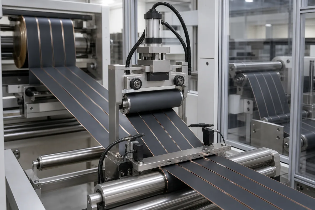
Tension control system for lithium-ion battery electrode slitting and rewinding
Battery electrode slitting lines · unwind and rewind tension in newtons, slip shafts per lane, thin copper and aluminium foil
In battery cell production, coated electrode rolls are slit lengthwise into strips and each strip is rewound onto its own core. The tension control system on that machine is a magnetic-powder brake or closed-loop drive on the unwind, sensing and guiding through the knives, and differential (slip) shafts on the rewind that let each lane slip independently so all lanes wind at the same tension. Three questions decide the specification: the tension range in newtons for your web width and foil, how the rewind equalises tension across lanes, and what burr and edge-wave limits the slit strips must meet.
Tension control on lithium-ion battery electrode slitting and rewinding machines: unwind brakes or closed-loop unwind control, roll-diameter tracking and edge guiding, and differential (slip) rewind shafts for multi-lane winding of coated copper and aluminium foil. General load-cell and dancer tension control on unwind and rewind stands is covered on the Web tension control page; textile machines on the Fabric tension control page; textile tension sensors on the Textile tension sensor page; and core chucks on the Core chucking system page. Slitting knives and coating equipment are outside this page.
CNFX editorial research · Sources checked October 12, 2026 · 6 sources
Published unwind and rewind tension on three electrode slitters
Electrode slitter makers state tension in newtons for the whole web, next to speed, web width and roll size. The three machines below were published for cathode and anode sheets after intermittent or continuous coating. [1][2][3]
Editorial calculation: spread across the full web, Cykyo's 100 N maximum on a 400 mm base material is 100 ÷ 400 = 0.25 N/mm, and Jinye's 200 N unwind maximum on a 650 mm web is about 0.31 N/mm. These are averages at maximum width; narrower webs at the same force carry more per millimetre. [2][1]
Xiaowei prints its tension range as 0–100 Nm, a torque unit, while the other two state newtons; ask the maker to confirm whether the figure is web tension or brake torque before comparing. [3]
Cykyo recommends 15–40 mm of edge waste on each side after slitting. Editorial calculation: on its 400 mm maximum web that leaves 370 mm of usable width at 15 mm per side and 320 mm at 40 mm per side, to be divided among the standard four slits of 30–270 mm each. [2]
Machine
Tension
Speed
Web and rolls
Unwind control
Wuxi Jinye ZY75Q-VC600-S80
Unwind 20–200 N; rewind 20–100 N
0–80 m/min
Max 650 mm wide; unwind and rewind up to Ø600 mm
Magnetic-powder clutch constant tension; edge or centre guide ±0.1 mm [1]
Cykyo continuous electrode slitter
Max 100 N
Mechanical 0.2–50 m/min; operating 0.2–40 m/min
Max 400 mm base material; unwind Ø400 mm, rewind Ø350 mm
Closed-loop unwind tension with roll-diameter measurement [2]
Xiaowei automatic electrode slitter
Unwind 0–100; rewind 0–100 (unit printed as Nm)
0–50 m/min
Unwind Ø600 mm, rewind Ø500 mm; 0.05–0.3 mm thick
Magnetic-powder brake constant tension with photoelectric correction [3]
Give the slitter maker the electrode type (cathode or anode), foil material and thickness, coated thickness and coating pattern (intermittent or continuous), mother-roll width, diameter and core, number and width of slit lanes, line speed, required tension range, and the burr, width and rewind-neatness limits for the strips.
02
Slip shafts let each slit lane wind at the same tension
Wuxi Jinye's slitter rewinds onto two slip shafts to keep constant winding tension on each strip and all strips synchronised without breaks, with rewind tension tracked online and set on the touch screen. [1]
Xiaowei uses the same two-slip-shaft rewind and sets winding tension, slitting speed and slip-shaft pressure on its touch screen; traction is servo-driven and winding is controlled by an inverter and PLC. [3] Cykyo specifies dual-station 3-inch air-expanding differential shafts for rewinding and a 3-inch air-expanding shaft for unwinding. [2]
XW Machinery, a differential shaft maker, explains that each friction ring on the shaft slips independently according to web tension, and recommends ball-type shafts for low-tension, narrow-slit rewinding of film and battery separator and lug-type shafts where stronger grip is needed for foil and wide rolls. [6] Ask the slitter maker which shaft type, ring pitch and air-pressure range suit your narrowest lane and lowest tension.
03
Thin copper foil, burr height and edge wave on the slit strip
Dah Bah, a slitter maker, describes the anode as copper foil of 8–10 µm coated with graphite and notes that copper foils thinner than 8 µm call for slitting machines with finer precision and more delicate tension control. [4] Calemard, whose Spoolex electrode slitters unwind the web under controlled tension before slitting, puts the cathode current collector in aluminium and the anode in copper, and warns that burrs can pierce the separator or bridge the electrodes and cause short circuits. [5]
Sources for the table: Wuxi Jinye [1] and Xiaowei [3]. Editorial note: the limits come from makers' product pages, measured by their own methods; agree the measuring method for burr height and edge wave with the slitter maker before acceptance trials on your own electrode.
Strip quality limit
Wuxi Jinye
Xiaowei
Edge burr
≤ 7 µm
≤ 5 µm
Slit width tolerance
≤ ±0.3 mm
±0.05 mm
Edge wave or serpentine
≤ ±0.05 mm/m
< ±0.05 mm
Rewind neatness
≤ ±0.5 mm per coil
printed as "±05mm"; confirm with the maker
04
Electrode slitting tension brief
Paste it into your enquiry below or into an email to a maker, then replace every bracket.
Electrode: [cathode or anode; foil material and thickness; coating thickness; intermittent or continuous coating]
Mother roll: [width; diameter; core size]
Slitting: [number of lanes; lane widths; edge waste]
Tension: [unwind range in N; rewind range in N]
Rewind: [differential shaft type; core size; rewind diameter]
Speed: [operating line speed]
Quality: [burr; width tolerance; edge wave; rewind neatness]
XW Machinery makes ball- and key-type differential shafts for slitter rewinders; Precision Converting and Sunrise Group supply tension controllers, sensors, magnetic-particle clutches and brakes, and air shafts.
XW Machinery
Manufacturing site to be confirmed for the order
Lists differential air shafts for slitting and rewinding (including lithium battery materials), air shafts and magnetic powder clutches 6–400 Nm.
Explore company information and manufacturing capabilities, then discuss the scope of your project with a relevant supplier.
Share this page
Compiled and source-reviewed by the CNFX editorial team.
Each manufacturer above links to the page on that company's own website where the product is listed, with the date we checked it. How we source and review
· Page last updated 13 October 2026
Buyer questions
What tension range do battery electrode slitters use?
Published examples include 20–200 N unwind and 20–100 N rewind on a Wuxi Jinye machine, and a 100 N maximum on a Cykyo slitter with a 400 mm web. [1][2]
Why do electrode slitters rewind on slip shafts?
Two slip shafts keep each slit strip at the same winding tension and all strips synchronised, as Wuxi Jinye and Xiaowei describe. [1][3]
How thin is the copper foil being slit?
Dah Bah gives 8–10 µm for anode copper foil and says thinner foils need more delicate tension control. [4]
What burr limits do slitter makers publish?
Wuxi Jinye states ≤7 µm and Xiaowei ≤5 µm edge burr. [1][3]
Sources and what still needs a direct check
Sources checked 2026-10-12. Wuxi Jinye, Cykyo, Xiaowei, Dah Bah and Calemard are slitter makers describing their own machines; XW Machinery describes its differential shafts.