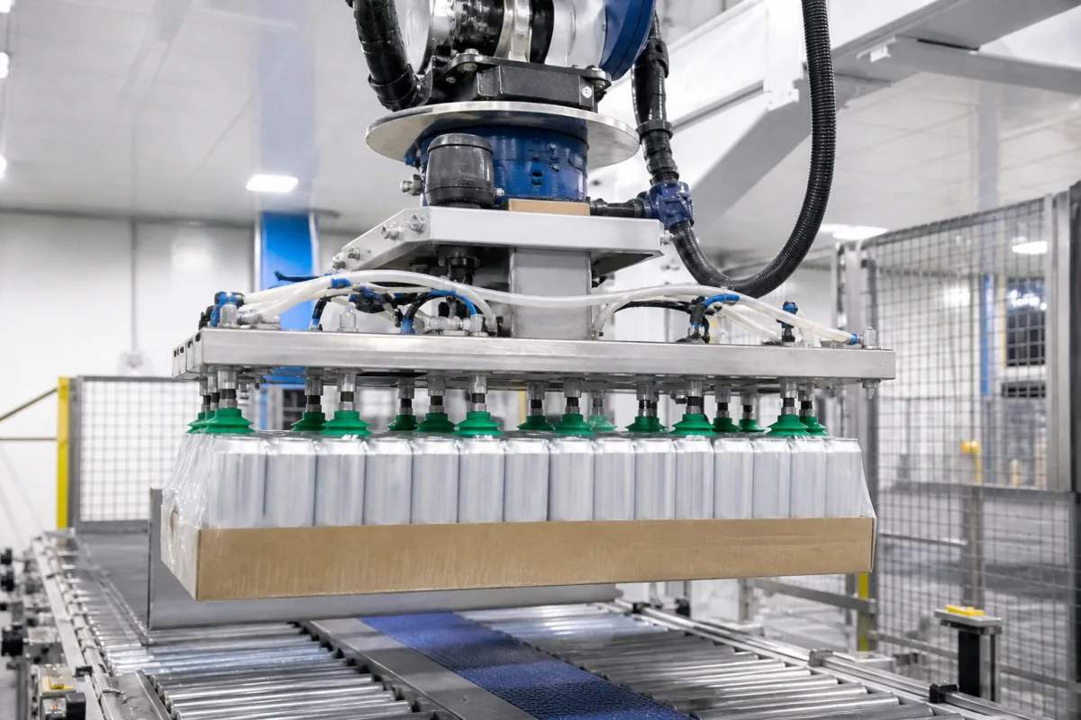
Vacuum gripper head with one bellows cup per can: picking beverage containers by their ends, sized to slim and sleek can necks
Beverage cans and bottles · a robot head that lands one bellows cup on the end of each container instead of one pad across the whole case
Lifting a layer or a tray of cans is a different job when every can has its own suction cup. Each cup has to land on a small, recessed can end without knocking the neighbours, hold a filled can through the robot's acceleration, and let go cleanly when the can reaches the tray or the next conveyor. This page deals with that per-container head: how big the cup and its housing may be for a given can neck, how much one cup holds, and how the can is kept centred and in its label orientation while it hangs from the cup.
Robot and gantry vacuum heads that pick beverage cans, and bottles with a flat closure, by their ends with one bellows suction cup per container, for loading trays and cases, gathering multipacks and re-forming layers: cup and gripper diameter against can neck size, the lift of one cup, alignment bodies, and release. Vacuum end-effectors that grip the board or film of whole cases and trays, with foam pads and zone valves, are covered on the Vacuum gripper end-effector for palletizing beverage cases and cartons page; sizing and materials of individual cups on the Vacuum suction cup page; block distributors that feed two or more cups from one generator on the Vacuum manifold (block distributor) for multi-cup vacuum grippers page; soft-landing cups for lenses and glass on the Vacuum gripper end-effector for lenses and marking-sensitive parts page; cameras that locate containers on a moving belt for the robot on the Conveyor-tracking vision guidance for robot picking of bottles and containers page.
CNFX editorial research · Sources checked October 13, 2026 · 4 sources
Slim and sleek can ends: 50.0 and 52.4 mm necks set how wide each cup and its housing may be
Ardagh Metal Packaging's customer sheets for two aluminium cans give the dimensions a per-can head has to respect: the neck the end is seamed onto, the body the neighbouring grippers must clear, and the can's own strength.
A gripper patent filed by Anheuser-Busch InBev sets the outer limit for the head: its gripper device may be less than around 53 mm across to handle slim cans with 200 series lids, or less than around 58 mm for sleek cans with 202 series lids, and it names 58, 66 and 76 mm as other standard can diameters. [1] Keeping the gripper narrower than the can is what lets the patent's grippers pick cans standing in side contact and set them down in rows and columns touching on four sides, or nested touching on three. [1]
Editorial comparison: the patent's 53 mm limit for slim cans sits 0.4 mm under the 53.4 mm maximum body diameter on Ardagh's slim-can sheet, and its 58 mm limit for sleek cans sits 0.1 mm under the 58.1 mm maximum on the sleek-can sheet, so on cans gathered in contact the grippers stand almost shoulder to shoulder. [1][3][2] The cup itself lands inside the seamed end, whose neck plug is 50.0 mm on the slim can and 52.4 mm on the sleek can; the flat area of the end that the lip seals on lies inside that diameter, and its size comes from the end supplier's drawing.
Send the can or end drawing (end series and the diameter of the flat panel the cup will seal on), the body diameter, and the pattern the cans are to be set down in: rows and columns, nested, or spaced.
02
Holding one filled can by its lid: a 40 mm cup at −60 kPa against SMC's horizontal-lift factor of 4
SMC's selection data for its ZPT/ZPX bellows and flat pads give the theoretical force of a pad and the safety factor to divide it by; applied to one can, they show how much margin a single cup has.
Editorial calculation: dividing SMC's 75.6 N for a ø40 pad at −60 kPa by the horizontal factor of 4 gives about 18.9 N, or roughly 1.9 kg, for one cup. [4] A 330 ml sleek can weighs 9.6 g empty on Ardagh's sheet [2]; assuming a drink about as dense as water, 330 ml adds about 0.33 kg, so the filled can weighs about 0.34 kg plus its end, and the 1.9 kg allowed for one ø40 cup at that vacuum is more than five times that. The ø50 pad, at 118 N theoretical, is as wide as the 50.0 mm neck of a slim can, leaving no room for its lip inside that end. [4][3]
The Anheuser-Busch InBev gripper runs much deeper: it describes the pressure inside its bellows cup in the gripping configuration as around 90 kPa, a deep vacuum close to full vacuum, and lists a fast, positive release using a needle valve and a flow-reversing solenoid for high throughputs. [1] Both Ardagh sheets specify a 675 N minimum column strength, the axial load figure to set against the force each cup and alignment body puts on a can end when the head lands. [2][3]
SMC figure
Value
Theoretical lifting force
Vacuum pressure (kPa) × pad area (cm²) × 0.1, in N [4]
Safety factor, pad face horizontal (lifting from above)
Ask for the cup diameter and material, the vacuum the head holds on a can end at the offered generator, and the acceleration of the robot or gantry, so the single-cup force can be checked against the filled can.
03
Centring each can against an alignment ring and keeping label rotation under 3°
Gathering cans into a multipack with every label facing the same way needs more than a cup that holds; the Anheuser-Busch InBev patent describes how its head also centres and orients each can.
The patent's gripper carries an alignment body and a bellows cup at the same end. In the extended state the cup lip projects beyond the alignment body and touches the can first; when vacuum is applied the bellows shortens and pulls the can up against the alignment body, which centres the can on the gripper axis and squares its end to it. [1] The moulded bellows is fixed to the alignment body against rotation and resists twisting, so the can's rotational position is not disturbed; once seated, the gripper can be turned to orient decoration or codes uniformly for placement in secondary packaging. [1]
The document states that rotational misalignment becomes readily detectable above about 3°, and that releasing the can first from the alignment body and only then from the cup lip keeps rotational disturbance well below that. [1] It contrasts this with vacuum end-effectors that are essentially large pads acting on the top rims of a whole group of empty or sealed containers. [1] Further functions it lists for a per-container head are an integrated sensor that detects a failed pick or a dropped can, tool-less exchange of alignment bodies for different can-end series, and identification of which gripper and alignment body sits in each docking station before production starts. [1]
State whether cans must keep or gain a set label orientation in the pack, how a dropped or missed can is to be detected, and how many can-end series the head must change between.
04
Data for a per-can vacuum gripper head enquiry
Paste it into your enquiry below or into an email to a maker, then replace every bracket.
Containers: [can size and end series; bottles and closure type if any; filled or empty]
Pick pattern: [cans per pick; spacing or side contact; rows and columns or nested]
Place pattern: [tray, case, multipack, conveyor; label orientation required or not]
Rate: [picks per minute; robot or gantry; acceleration]
Vacuum: [compressed air for ejectors or central pump; available supply]
Changeover: [end series to be handled; time allowed per change]
Monitoring: [per-can pick confirmation; dropped-can detection]
Explore company information and manufacturing capabilities, then discuss the scope of your project with a relevant supplier.
Share this page
Compiled and source-reviewed by the CNFX editorial team.
Each manufacturer above links to the page on that company's own website where the product is listed, with the date we checked it. How we source and review
· Page last updated 13 October 2026
Buyer questions
How wide can a per-can gripper be?
The Anheuser-Busch InBev patent gives less than around 53 mm for slim cans with 200 series lids and less than around 58 mm for sleek cans with 202 series lids, so grippers can pick cans standing in side contact. [1]
What neck diameters do slim and sleek can ends sit on?
Ardagh's sheets give a 50.0 ±0.3 mm neck plug for a 250 ml slim can and 52.4 ±0.3 mm for a 330 ml sleek can. [3][2]
Is one 40 mm cup enough for a filled can?
SMC lists 75.6 N theoretical for a ø40 pad at −60 kPa and a factor of 4 for horizontal lifting; dividing gives about 18.9 N (editorial calculation), more than five times the weight of a filled 330 ml can taken as about 0.34 kg plus its end. [4][2]
How does the head avoid turning the can?
In the patent, the bellows cup is fixed against rotation and pulls the can against an alignment body; release from the alignment body before the cup keeps rotation well below the 3° at which misalignment becomes readily detectable. [1]
Sources and what still needs a direct check
Sources checked 2026-10-13. Ardagh Metal Packaging's customer sheets give the body, neck and strength data of a slim and a sleek aluminium can; SMC's vacuum pad catalogue gives the theoretical lifting force table and safety factors; an Anheuser-Busch InBev European patent application describes a per-can bellows gripper with an alignment body.