Editorial Technical Reference

Inert Gas Purge System

This page explains how Inert Gas Purge System is classified within Chemical Manufacturing. Technical values and manufacturer relationships are research references; confirm the current specification and supplier evidence for each order.

Technical Definition & Core Assembly

A safety system that uses inert gases to displace oxygen and flammable vapors from catalyst handling equipment to prevent combustion and oxidation during loading/unloading operations.
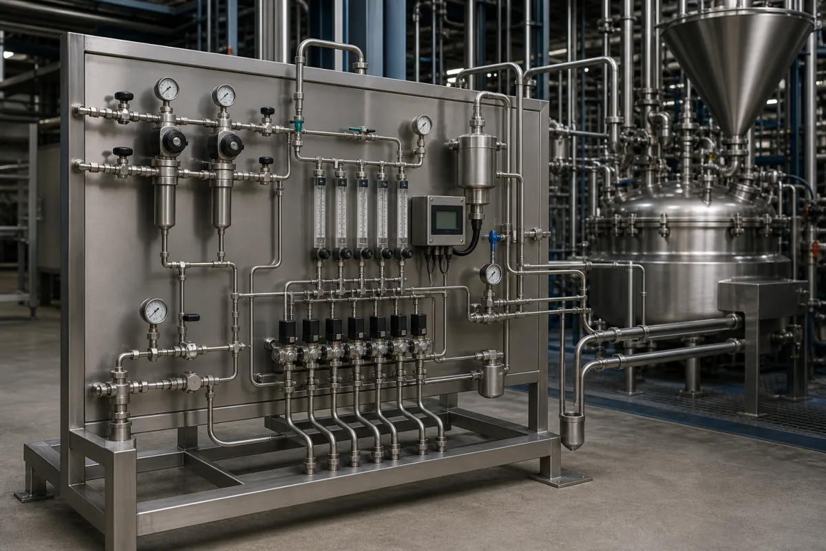
Representative product image. Confirm appearance and specifications with the manufacturer.

Product Specifications

Technical details and manufacturing context for Inert Gas Purge System

Definition
The Inert Gas Purge System is a critical safety component within the Automated Catalyst Loading and Unloading System. Its primary function is to maintain an oxygen-free environment in reactor vessels, transfer lines, and catalyst storage containers during automated transfer processes. By introducing inert gases such as nitrogen or argon, the system displaces atmospheric oxygen and residual flammable hydrocarbons, thereby preventing fire, explosion, and unwanted oxidation of sensitive catalyst materials. The system operates by creating a positive pressure flow of inert gas through enclosed spaces. Gas is introduced at strategic inlet points, flows through vessels and piping to sweep out oxygen and contaminants, and exits through controlled vents or exhaust ports. Pressure regulators, flow meters, and oxygen analyzers monitor and control the purge process to ensure complete inertization before catalyst transfer begins. Constructed with corrosion-resistant materials, the system is designed for chemical service. Key parameters include a purge gas flow rate of 50–200 m³/h, an oxygen concentration target of ≤1%, a purge cycle time of 15–30 minutes, and an operating pressure of 1.0–1.6 bar. Gas purity is ≥99.9%, and operating temperature ranges from -20°C to 80°C. The enclosure rating is IP54–IP65 (IEC 60529), supply voltage is 220–240 V AC, and power consumption is 0.5–2.0 kW. The wetted parts are made of stainless steel 316L (ASTM A240), with PTFE seals and nickel alloy fittings. The skid-mounted unit weighs 150–300 kg and has approximate dimensions of 1200×800×1500 mm. All values are reference ranges and must be verified for the specific model and application with the legal manufacturer or supplier.
Working Principle
The system operates by creating a positive pressure flow of inert gas through the enclosed spaces of the catalyst handling equipment. Gas is introduced at strategic inlet points, flows through the vessels and piping to sweep out oxygen and contaminants, and exits through controlled vents or exhaust ports. Pressure regulators, flow meters, and oxygen analyzers monitor and control the purge process to ensure complete inertization before catalyst transfer begins.
Common Materials
Stainless Steel 316L, PTFE Seals, Nickel Alloy Fittings
Technical Parameters
ParameterTypical rangeNotes & selection driver
Purge Gas Flow RateRequired50–200 m³/hVolumetric flow rate of inert gas during purge cycle
Oxygen Concentration TargetRequired≤1 %Maximum allowable oxygen concentration after purge completion
Purge Cycle TimeRequired15–30 minutesTime required to achieve target oxygen concentration
Operating PressureRequired1.0–1.6 barMaximum system pressure during purge operation
Gas Purity≥99.9 %High purity to avoid introducing contaminants.
Maximum Operating Temperature80 °CAbove this, seals may degrade.
Minimum Operating Temperature-20 °CBelow this, materials may become brittle.
Enclosure RatingIP54–IP65Protection against dust and water jets.IEC 60529
Supply Voltage220–240 V ACSingle phase, 50/60 Hz.
Power Consumption0.5–2.0 kWDepends on flow rate and control system.
Material of Wetted Parts316LCorrosion resistant for chemical service.ASTM A240
Weight150–300 kgSkid-mounted unit, varies with configuration.
Dimensions (L×W×H)1200×800×1500 mmApproximate footprint for standard unit.

Ranges are indicative industry figures for RFQ preparation, not a supplier commitment. Confirm every value and standard with the legal manufacturer before ordering.

Components / BOM
  • Inert Gas Supply Manifold
    Distributes inert gas from source to multiple purge points with individual control valves
    Material: Stainless Steel 316L
  • Oxygen Analyzer
    Continuously monitors oxygen concentration in purge stream and vessel atmosphere
    Material: Stainless Steel Housing with Electrochemical Sensor
  • Flow Control Valve
    Regulates inert gas flow rate to maintain consistent purge conditions
    Material: Stainless Steel with PTFE Seats
  • Pressure Relief Device
    Prevents over-pressurization of vessels during purge operations
    Material: Stainless Steel Spring Mechanism
  • Pressure Regulator
    Drops the supply pressure to the purge pressure and holds it steady.
  • Vent / Exhaust Port
    Lets the displaced oxygen and vapours out so the purge can actually sweep through.

Industry Taxonomies & Aliases

Commonly used trade names and technical identifiers for Inert Gas Purge System.

Applied To / Applications

This component is essential for the following industrial systems and equipment:

Industrial Ecosystem & Supply Chain Structure

Complementary Systems
Downstream Applications
Specialized Tooling

Application Fit & Sizing Matrix

Operational Limits
pressure: 0 to 10 bar(g)
flow rate: 10 to 500 Nm³/h
temperature: -40°C to 150°C
oxygen level: <5% v/v (typical), <2% v/v (for pyrophoric catalysts)
Media Compatibility
✓ Nitrogen (N₂) purge gas ✓ Catalyst powders (zeolite, alumina-based) ✓ Stainless steel 316L equipment
Unsuitable: Chlorinated hydrocarbon environments (risk of stress corrosion cracking)
Sizing Data Required
  • Vessel volume (m³) to be purged
  • Required purge cycle time (minutes)
  • Initial oxygen concentration in vessel (% v/v)

Reliability & Engineering Risk Analysis

Failure Mode & Root Cause
Oxygen ingress due to seal degradation
Cause: Deterioration of valve seals or flange gaskets from chemical exposure, thermal cycling, or mechanical wear, compromising system integrity and allowing atmospheric oxygen to enter
Pressure regulator failure leading to inadequate purge flow
Cause: Contamination of regulator internals by particulates or moisture, or diaphragm fatigue from cyclic operation, resulting in inconsistent inert gas delivery
Maintenance Indicators
  • Audible hissing or whistling from valves or connections indicating gas leaks
  • Visible condensation or frost on external surfaces of regulators or lines, suggesting moisture ingress or improper gas conditioning
Engineering Tips
  • Implement routine integrity testing with oxygen analyzers at critical points to detect seal failures early, and use compatible, high-quality sealing materials rated for the specific inert gas and operating conditions
  • Install and maintain particulate filters and moisture traps upstream of pressure regulators, and perform regular calibration and stroke testing of regulators to ensure consistent purge flow rates

Indicative industry ranges for design and RFQ preparation. Confirm the exact figures and applicable standard with the manufacturer before specifying.

Compliance & Manufacturing Standards

Applicable Standards
ISO 14175:2008 (Welding consumables - Gases and gas mixtures for fusion welding and allied processes) ANSI/ASME B31.3 (Process Piping) DIN EN 13445-3 (Unfired pressure vessels - Part 3: Design)

Quoted from the published standard.

Manufacturing Precision
  • Pipe Bore Diameter: +/-0.05mm
  • Flange Flatness: 0.1mm per 300mm diameter
Quality Inspection
  • Helium Leak Test (per ASME BPVC Section V)
  • Pressure Decay Test (per ISO 20486)

Manufacturers of Inert Gas Purge System

Manufacturer profiles associated with Inert Gas Purge System.

Sourcing Inert Gas Purge System from China?
Tell us your specification and target quantity — we will match it against manufacturer records and come back with the factories that fit.
Request manufacturers We manufacture this

Manufacturer listings support early research and capability understanding. They are not certification, ranking, or transaction guarantees.

Technical documentation
Request current drawings, revision history, and a signed specification sheet.
Manufacturing capability
Verify equipment lists, process limits, capacity, and representative production evidence.
Inspection readiness
Confirm test methods, calibrated equipment, sampling plans, and traceable reports.
Supplier transparency
Check the legal entity, factory address, ownership, certifications, and direct contacts.

CNFX does not score or rank suppliers. Buyers must verify all claims and documents with the legal manufacturer before ordering.

Supply Chain Compatible Machinery & Devices

Automated Batch Crystallization System

Automated system for controlled crystallization of chemical compounds in batch processes.

Explore Specs →
Automated pH Monitoring and Dosing System

Automated system for continuous pH monitoring and chemical dosing in process streams.

Explore Specs →
Automated Powder Dispensing and Blending System

Automated system for precise dispensing and homogeneous blending of powdered chemicals.

Explore Specs →
Automated Viscosity Control and Mixing System

The Automated Viscosity Control and Mixing System is an industrial automation solution designed for continuous monitoring and adjustment of viscosity in chemical mixing and blending operations.

Explore Specs →

Frequently Asked Questions

What is the purpose of the Inert Gas Purge System?

It displaces oxygen and flammable vapors from catalyst handling equipment to prevent combustion and oxidation during loading/unloading operations.

Which gases are typically used?

Inert gases such as nitrogen or argon are used, with a purity of at least 99.9% to avoid introducing contaminants.

What are the key operating parameters?

Flow rate 50–200 m³/h, oxygen target ≤1%, cycle time 15–30 min, operating pressure 1.0–1.6 bar, temperature range -20 to 80°C. Verify with manufacturer.

What materials are used in construction?

Wetted parts are stainless steel 316L, with PTFE seals and nickel alloy fittings, suitable for chemical service.

Data Basis

Editorial classification, named public sources where available, and source-reviewed manufacturer records.

Preliminary Technical Classification
This page supports structured research, RFQ preparation, and supplier evaluation. It does not replace buyer-led supplier qualification, standards review, or technical approval.
Buyer enquiry

Request manufacturing insight for Inert Gas Purge System

Ask for use case, specification boundaries, supplier type, and RFQ preparation information for this product.

Where it goes
Straight to the CNFX editorial desk, and to the manufacturer if this product is linked to a claimed profile. Nothing is broadcast to a supplier list.
Your details stay here
We do not sell or rent enquiry data, and we do not add you to a mailing list. Used only to answer this request.
No commission, no middleman
CNFX is a directory. We take no cut of any order and never negotiate on a supplier's behalf.
What we don't claim
A listing is not an endorsement. Qualify every supplier and verify every figure yourself before ordering.

Your business information is used only to process this request.

Thank you! Your message has been sent. We'll respond within 1–3 business days.
Sorry, we couldn't send your message. Please try again, or email us at contact@cnfx.com.

Need to Manufacture Inert Gas Purge System?

Compare manufacturer profiles with relevant product and process capability.

Previous Product
Industrial Rotary Drum Vacuum Filter
Next Product
Ingredient Hopper
Get QuotesChat