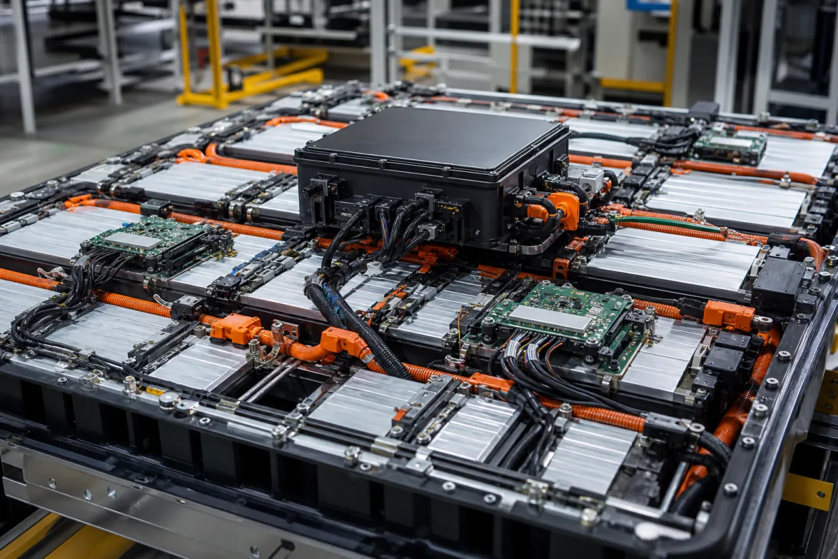
Distributed (master–slave) battery management system for module-based traction packs
Large traction and module-based packs · Cell monitoring boards on each module, daisy-chain or ring links to a master controller, chain length and scan time
In a distributed (master–slave) battery management system, each battery module carries its own cell-monitoring board that measures cell voltages and temperatures and balances the cells, and these boards pass their data along an isolated daisy chain — or a ring — to a master controller that runs the pack-level functions and talks to the vehicle or system. Ask three things first: how many cells each monitoring board covers and how many boards one chain can carry, how fast and how accurately the whole pack is scanned, and what happens to communication if a link in the chain breaks.
Battery management systems built as a master controller plus cell-monitoring boards mounted on each module of a large lithium-ion or solid-state traction or storage pack, linked by isolated daisy-chain, ring or similar module-to-master links. Single-board BMS and protection boards for packs of one module are covered on the Battery management system page; battery cells, complete packs, BMS test equipment and power semiconductors are outside this page.
CNFX editorial research · Sources checked October 12, 2026 · 3 sources
Count cells per monitoring board and boards per chain
Renesas's ISL94212A supervises up to 12 series-connected cells, talks to the host microcontroller over SPI and to other ISL94212A devices over a proprietary two-wire daisy chain, and can daisy-chain up to 14 devices to monitor up to 168 cells; it offers manual, timed and automatic balancing and is specified for −40 to +85 °C. [1] TI's BQ79616 monitors 16 series cells and stacks through an isolated differential daisy chain with an optional ring architecture, carrying an embedded fault signal and heartbeat on the communication line, with the BQ79600 as the UART/SPI bridge to the host. [2]
Infineon's TLE9012DQU monitors up to 12 cells with a 16-bit delta-sigma ADC per cell, a 200 mA balance switch, an isolated UART at 2 Mbit/s, hot-plugging support and ISO 26262 ASIL D compliance; Infineon lists high-voltage automotive BMS, energy storage and e-bike packs among its uses. [3]
Editorial calculation (example pack of 96 cells in series, chosen for illustration): with 16-cell BQ79616 devices the pack needs 96 ÷ 16 = 6 monitoring devices; with 12-cell ISL94212A or TLE9012DQU devices it needs 96 ÷ 12 = 8, within the ISL94212A's limit of 14 devices (168 cells) per chain. A 192-cell pack on 12-cell devices would need 16, beyond that limit, so ask how the supplier splits longer packs. [2][1][3]
Give the supplier the cell chemistry and format, cells in series and in parallel, the module layout and how many cells each module holds, the pack voltage range, the distance between modules and the master, the required link topology (daisy chain or ring), the functional-safety target, the vehicle or system interface (CAN or other), and the temperature range.
02
Check how fast and how accurately the whole pack is scanned
Renesas lists ±10 mV cell-voltage accuracy at 13-bit resolution, ±180 mV pack-voltage accuracy and a cell scan rate of 19.5 µs per cell, or 234 µs for 12 cells, for the ISL94212A. TI lists ±1.5 mV ADC accuracy for the BQ79616 with all cell channels measured within 128 µs, a redundant path for voltage and temperature diagnostics, configurable post-ADC digital low-pass filters, bus-bar connection and measurement support, and internal balancing at 240 mA with thermal pause and resume. [1][2]
Editorial note: these are device figures; the master sees each module only after the chain has passed the data along, so ask the supplier for the time from a cell event to the master's reaction across your full chain, not the scan time of one device.
Editorial calculation: at TI's 240 mA balancing current, removing 1 Ah of imbalance from one cell takes 1 ÷ 0.24 ≈ 4.2 h of continuous balancing; Infineon's 200 mA switch would take 1 ÷ 0.2 = 5 h, before any thermal pauses. [2][3]
03
Where each function sits: module board, chain and master
Part
Role
Published example
Cell monitoring board (slave)
Measures cell voltages and temperatures and balances cells on one module.
12 cells (ISL94212A, TLE9012DQU) or 16 cells (BQ79616) per device. [1][3][2]
Isolated module-to-module link
Carries data between boards across module voltage levels.
Redundant path and heartbeat (BQ79616); secondary ADC (TLE9012DQU). [2][3]
04
Pack-level values to agree with a distributed BMS supplier
Device datasheets give per-chip figures; current accuracy, SOC accuracy, quiescent current and the board's own size and protection come from the BMS supplier's design.
Field
Published values and meaning
Ask the supplier for
Operating voltage range (V DC)
Pack voltage the chain spans; ISL94212A pack accuracy ±180 mV. [1]
Paste it into your enquiry below or into an email to a maker, then replace every bracket.
Pack: [chemistry; cells series and parallel; modules]
Modules: [cells per module; spacing to master]
Link: [daisy chain or ring; isolation]
Measurement: [cell accuracy; scan time; temperatures]
Balancing: [current; strategy]
Safety and interface: [ASIL target; CAN or other]
Explore company information and manufacturing capabilities, then discuss the scope of your project with a relevant supplier.
Share this page
Compiled and source-reviewed by the CNFX editorial team.
Each manufacturer above links to the page on that company's own website where the product is listed, with the date we checked it. How we source and review
· Page last updated 13 October 2026
Buyer questions
How many cells can one daisy chain monitor?
Renesas lists up to 14 ISL94212A devices in a chain, monitoring up to 168 cells. [1]
Why use a ring instead of a daisy chain?
TI offers an optional ring architecture on the BQ79616's isolated daisy chain, with a fault signal and heartbeat carried on the line. [2]
How accurate are cell monitoring boards?
It depends on the monitor IC: TI lists ±1.5 mV for the BQ79616 and Renesas ±10 mV for the ISL94212A. [2][1]
Sources and what still needs a direct check
Sources checked 2026-10-12. Renesas, Texas Instruments and Infineon describe their own cell-monitoring ICs, the devices that sit on each module board of a distributed BMS.