Editorial Technical Reference

Controller Board

This page explains how Controller Board is classified within Computer, Electronic and Optical Product Manufacturing. Technical values and manufacturer relationships are research references; confirm the current specification and supplier evidence for each order.

Technical Definition & Core Assembly

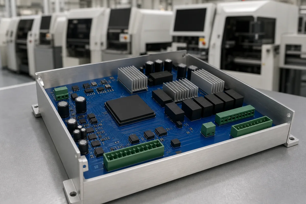
The main printed circuit board (PCB) that processes inputs and controls outputs for an HMI touchscreen system.

Representative product image. Confirm appearance and specifications with the manufacturer.

Product Specifications

Technical details and manufacturing context for Controller Board

Definition
A controller board is the core electronic component within an HMI touchscreen, responsible for interpreting touch inputs, executing the user interface logic, managing communication with external devices or PLCs, and controlling the display output. It integrates the microprocessor, memory, communication interfaces, and power regulation circuits necessary for the touchscreen's operation. The board is designed for industrial environments, with a supply voltage of 24 V DC (±10%), power consumption ranging from 5 to 15 W, a listed operating temperature range of -20 to 70 °C, and a listed storage temperature range of -40 to 85 °C. Both temperature ranges must be confirmed for the specific board. IEC 60068-2-1 and IEC 60068-2-2 are cold and dry-heat test methods and do not establish these ranges. The listed humidity is 10 to 90% RH (non-condensing), with IEC 60068-2-78 retained as a verification reference. Ingress protection is rated IP54 to IP65 (IEC 60529), depending on the enclosure. The processor clock speed ranges from 400 to 800 MHz, RAM from 128 to 512 MB, and flash storage from 256 to 1024 MB. The PCB is made of FR-4 glass epoxy substrate with copper traces, solder (tin/lead or lead-free), and electronic components such as ICs, resistors, and capacitors. PCB thickness is 1.6 mm (±0.1 mm, IPC-6012), copper weight is 1 to 2 oz (IPC-6012), and board dimensions are customizable from 100×70 mm to 200×150 mm. Weight ranges from 150 to 300 g. These values are reference ranges; actual specifications must be confirmed with the manufacturer for the specific model. The board is a component used in the manufacturing of computer, electronic, and optical products. It is not a standalone product but is integrated into HMI systems. For procurement, verify that the board meets the required standards and parameters for your application.
Working Principle
The board receives low-voltage electrical signals from the touch sensor overlay. Its microprocessor executes firmware to interpret these signals as specific screen coordinates or gestures. Based on the programmed interface logic, it generates corresponding output signals to update the display and/or send commands (e.g., via Ethernet, serial ports) to connected industrial controllers or machinery. The board manages power regulation to ensure stable operation. It also handles communication protocols for data exchange with external devices. The firmware is stored in flash memory and executed from RAM. The board's operation is bounded by its electrical and environmental limits; exceeding them may cause resets or damage. For selection, consider the required processor speed, memory, and I/O interfaces. Verification should include testing under expected temperature and humidity conditions. Maintenance signals include unexpected resets or communication errors. Failure boundaries include voltage outside 24 V ±10%, temperature beyond -20 to 70 °C, or humidity above 90% RH.
Common Materials
FR-4 (Glass Epoxy PCB Substrate), Copper (Traces), Solder (Tin/Lead or Lead-free), Electronic Components (ICs, Resistors, Capacitors)
Technical Parameters
ParameterTypical rangeNotes & selection driver
Supply Voltage24 ±10% V DCOutside this range the board may reset or be damaged.
Power Consumption5–15 WDepends on display size and backlight.
Operating Temperature-20–70 °CExtended range may require conformal coating.
Storage Temperature-40–85 °CNon-operating.
Humidity10–90 % RHNon-condensing.IEC 60068-2-78
Ingress ProtectionIP54–IP65Higher IP requires sealed enclosure.IEC 60529
Processor Clock Speed400–800 MHzHigher speed for complex graphics.
RAM128–512 MBMore RAM for multitasking.
Flash Storage256–1024 MBFor firmware and data logging.
PCB Thickness1.6 ±0.1 mmStandard thickness for rigidity.IPC-6012
Copper Weight1–2 ozHigher for high-current traces.IPC-6012
Weight150–300 gDepends on board size and components.
Board Dimensions100×70–200×150 mmCustomizable to fit enclosure.

Ranges are indicative industry figures for RFQ preparation, not a supplier commitment. Confirm every value and standard with the legal manufacturer before ordering.

Components / BOM
  • Circuit Board
    The board itself: the substrate and copper traces that carry power and signals between the parts on it.
  • Microprocessor (CPU)
    Executes the system firmware and application logic, processes touch inputs, and manages all board functions.
    Material: Silicon (Semiconductor)
  • Memory (RAM/Flash) Part
    Stores the operating system, application software, and temporary data during operation.
    Material: Silicon (Semiconductor)
  • Power Regulator Circuit
    Converts and stabilizes the input voltage to the various levels required by different components on the board.
    Material: Electronic Components (ICs, Inductors, Capacitors)
  • Communication Interface ICs Part
    Provide the physical layer and protocol handling for serial, Ethernet, or other communication standards.
    Material: Silicon (Semiconductor)
  • Display Interface (LVDS/TTL Connector) Part
    Provides the electrical connection and signal protocol to drive the LCD panel of the touchscreen.
    Material: Copper, Plastic (Connector Housing)

Applied To / Applications

This component is essential for the following industrial systems and equipment:

Industrial Ecosystem & Supply Chain Structure

Complementary Systems
Downstream Applications
Specialized Tooling

Application Fit & Sizing Matrix

Operational Limits
pressure: N/A (board-level component, not exposed to process pressure)
other spec: Humidity: 10% to 90% non-condensing, Vibration: 5g max, Shock: 50g peak
temperature: 0°C to 70°C (operating), -40°C to 85°C (storage)
Media Compatibility
✓ Clean indoor environments ✓ Control cabinets with proper EMI shielding ✓ Dry industrial settings with dust protection
Unsuitable: Wet or corrosive atmospheres without IP-rated enclosure
Sizing Data Required
  • Required I/O count (digital/analog)
  • Processor performance needs (based on HMI complexity)
  • Communication protocols required (Ethernet, serial, etc.)

Reliability & Engineering Risk Analysis

Failure Mode & Root Cause
Thermal stress failure
Cause: Overheating due to poor ventilation, excessive ambient temperature, or component overload leading to solder joint cracks, delamination, or semiconductor degradation.
Electrochemical migration
Cause: Moisture ingress combined with ionic contamination on the PCB surface, creating conductive dendrites that cause short circuits or leakage currents between traces.
Maintenance Indicators
  • Intermittent or erratic system behavior (e.g., random resets, parameter drift, uncommanded outputs)
  • Visible signs of board damage (e.g., bulging/leaking capacitors, discolored/burned components, corrosion on connectors)
Engineering Tips
  • Implement strict environmental controls: maintain clean, dry operating conditions with proper airflow; use conformal coating in harsh environments; ensure stable power supply with surge protection.
  • Establish predictive maintenance: regularly monitor board temperature profiles with thermal imaging; perform periodic electrical testing (e.g., insulation resistance, power quality); maintain dust-free enclosures with scheduled cleaning.

Indicative industry ranges for design and RFQ preparation. Confirm the exact figures and applicable standard with the manufacturer before specifying.

Compliance & Manufacturing Standards

Applicable Standards
IEC 61010-1 Safety requirements for electrical equipment for measurement, control, and laboratory use CE marking for compliance with EU directives (e.g., EMC Directive 2014/30/EU, Low Voltage Directive 2014/35/EU)

Quoted from the published standard.

Manufacturing Precision
  • PCB trace width: +/-10% of nominal
  • Component placement accuracy: +/-0.1mm
Quality Inspection
  • In-Circuit Test (ICT) for electrical continuity and component verification
  • Environmental Stress Screening (ESS) including thermal cycling and vibration testing

Manufacturers of Controller Board

2 companies list this product among what they make. Company figures are quoted from each company's own website; every card states where the relationship came from.

Hongguang Display
Shenzhen, Guangdong, CN
Listed on the company's own website · profile compiled by CNFX from public sources
LeadsIntec Group
Guangdong, CN
Also makes: Rf Pcb, Fuel Level Sensor, Heavy Copper PCB and 9 more
Listed on the company's own website · profile compiled by CNFX from public sources

Manufacturer listings support early research and capability understanding. They are not certification, ranking, or transaction guarantees.

Technical documentation
Request current drawings, revision history, and a signed specification sheet.
Manufacturing capability
Verify equipment lists, process limits, capacity, and representative production evidence.
Inspection readiness
Confirm test methods, calibrated equipment, sampling plans, and traceable reports.
Supplier transparency
Check the legal entity, factory address, ownership, certifications, and direct contacts.

CNFX does not score or rank suppliers. Buyers must verify all claims and documents with the legal manufacturer before ordering.

Supply Chain Compatible Machinery & Devices

Industrial Smart Camera Module

The Industrial Smart Camera Module is a compact, self-contained vision processing unit designed for integration into industrial machinery and production lines.

Explore Specs →
Surface Mount Resistor

Passive electronic component for current limiting and voltage division in circuits

Explore Specs →
Surface Mount Capacitor

A surface mount capacitor is a fundamental electronic component used for energy storage, filtering, coupling, and decoupling in electronic circuits.

Explore Specs →
Surface Mount Technology (SMT) Pick-and-Place Machine

Automated machine that precisely places electronic components onto printed circuit boards.

Explore Specs →

Frequently Asked Questions

What is the supply voltage range for this controller board?

The supply voltage is 24 V DC with a tolerance of ±10%. Operating outside this range may cause the board to reset or be damaged. Always verify the exact voltage requirements with the manufacturer for your specific model.

What are the operating temperature limits?

The listed operating temperature range is -20 to 70 °C and the listed storage temperature range is -40 to 85 °C. Confirm both with the manufacturer for the specific board and application; extended ranges may require conformal coating. IEC 60068-2-1 and IEC 60068-2-2 are cold and dry-heat test methods and do not establish these ranges.

What ingress protection ratings are available?

The board is rated IP54 to IP65 according to IEC 60529. Higher IP ratings require a sealed enclosure. The actual rating depends on the enclosure design and must be verified with the manufacturer.

What are the memory and storage options?

RAM ranges from 128 to 512 MB, and flash storage from 256 to 1024 MB. More RAM supports multitasking, and flash is used for firmware and data logging. These are reference ranges; confirm the exact specifications with the manufacturer.

Data Basis

Editorial classification, named public sources where available, and source-reviewed manufacturer records.

Preliminary Technical Classification
This page supports structured research, RFQ preparation, and supplier evaluation. It does not replace buyer-led supplier qualification, standards review, or technical approval.
Buyer enquiry

Request manufacturing insight for Controller Board

Ask for use case, specification boundaries, supplier type, and RFQ preparation information for this product.

Where it goes
Straight to the CNFX editorial desk, and to the manufacturer if this product is linked to a claimed profile. Nothing is broadcast to a supplier list.
Your details stay here
We do not sell or rent enquiry data, and we do not add you to a mailing list. Used only to answer this request.
No commission, no middleman
CNFX is a directory. We take no cut of any order and never negotiate on a supplier's behalf.
What we don't claim
A listing is not an endorsement. Qualify every supplier and verify every figure yourself before ordering.

Your business information is used only to process this request.

Thank you! Your message has been sent. We'll respond within 1–3 business days.
Sorry, we couldn't send your message. Please try again, or email us at contact@cnfx.com.

Need to Manufacture Controller Board?

Compare manufacturer profiles with relevant product and process capability.

Previous Product
XY Positioning Stage
Last Product
Get QuotesChat