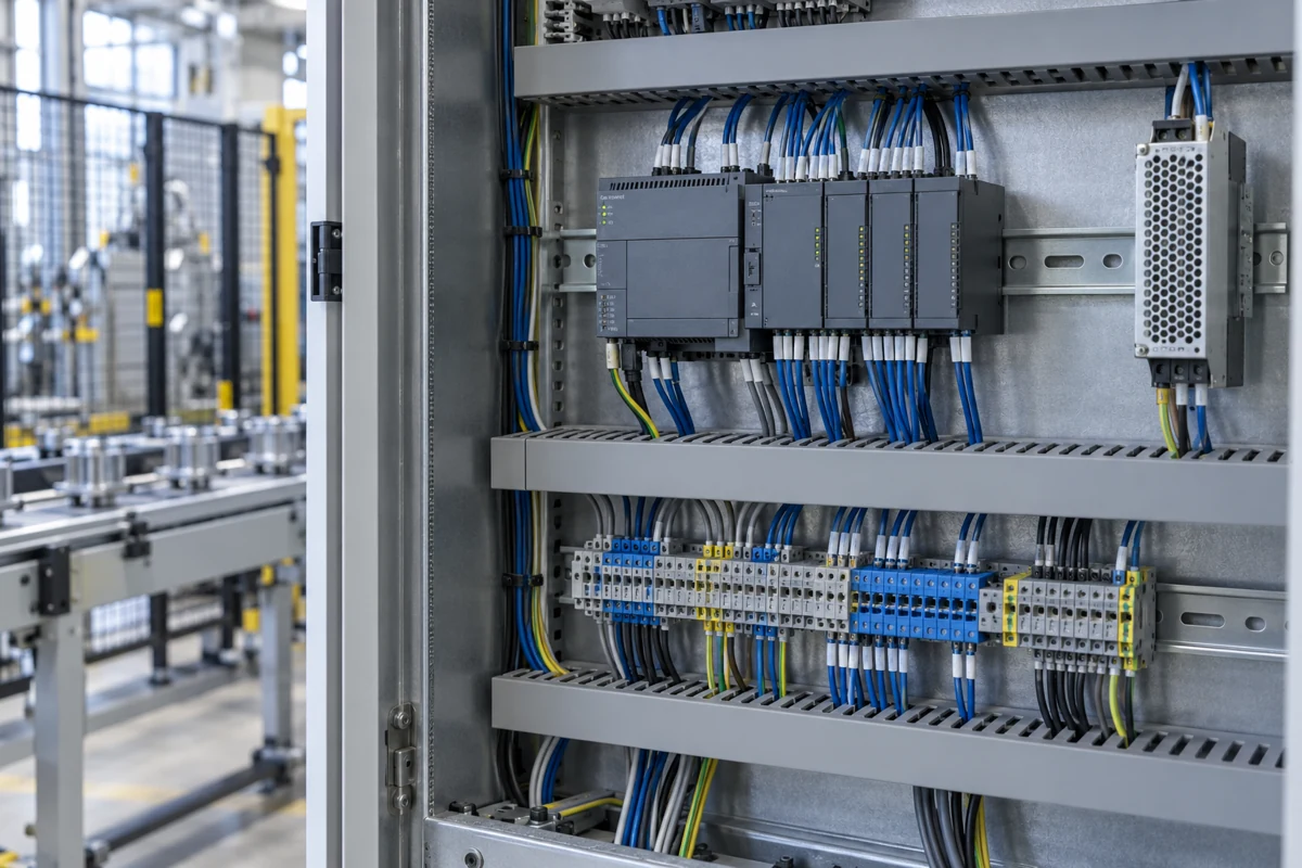
A PLC turns field signals into programmed machine actions. Follow the CPU and I/O path, size bus power, and check output loads. The Megmeet MC5000E examples distinguish CPU and expansion ratings, including conflicts that matter before wiring.
CNFX editorial research · Sources checked October 9, 2026 · 11 sources
In cyclic control, field inputs are represented in memory, the CPU executes the user logic, and the resulting output values are transferred to the output hardware. Communications and interrupts can affect scheduling; a processor benchmark alone does not establish machine response. Siemens describes its S7-1200 G2 default cycle as output update, input update and program execution, with interrupt tasks handled separately. That is an explanation of the mechanism, not an assertion that every PLC uses the same update order [11].
Functional structure / BOM reference
Role in control
How it appears in the hardware reference
CPU / processing unit
Executes the downloaded control program and coordinates I/O.
MC5000E is the controller; MC5000-0064ETN is an expansion module, not a CPU [5][7].
Power supply and bus power
Provides operating power to the controller and attached modules.
The CPU has a 24 VDC input; MP50AC220 is a separate AC power-supply option. Field loads are budgeted separately [5].
Input and output circuits
Inputs receive field signals; output switching stages command external loads.
CPU I/O and added digital or analog modules have their own channel and electrical ratings [3][6].
Program and data memory
Stores the control program and its working or retained data.
Ladder capacity is stated in steps. Program/data retention and real-time-clock retention describe different functions [5][3].
Communication interfaces
Exchange data with programming tools, field networks and remote I/O.
Ethernet, USB, RS485, SD and the expansion connector are identified on the MC5000E drawing. Remote couplers are separately selected products [5][3].
This is a functional structure reference, not a manufacturing BOM or a list of replaceable internal parts. The cited documents do not establish processor part numbers, PCB laminate, enclosure resin, connector plating or internal quantities. External cables, terminal blocks and expansion modules must be named separately in the order.
02
Select a CPU before counting expansion points
Megmeet’s 202405 catalogue separates CPUs, local I/O expansion and remote I/O couplers. Its MC5000E/MC5200E quick-start manual V2.0, dated 2025-06-17, identifies the CPU families explicitly [3][5].
Capacity is stated in steps, not kilobytes
V2.0 lists 320K ladder steps, up to 16 local expansion modules, 7 µs access per I/O module and maxima of 1024 local / 8192 remote points. These are controller-system limits, not built-in channel counts or a guarantee for any chosen module mix [5].
Execution speed and socket counts need a version-specific answer
V2.0 gives 4 ms / 100K steps and 8 Ethernet sockets. The 202405 catalogue tables give 2 ms / 100K and 7 sockets; the current product page says ≤2.2 ms for a 100K standard program. Obtain a matched CPU, firmware and test basis before using any figure as an acceptance limit. None is a measured response time for your complete machine [5][3][1].
Clock retention does not describe retained process data
V2.0 says the real-time clock retains for one week. The catalogue separately describes Flash program/data retention without a battery. Agree which recipes, counters, state variables and clock values must survive a power outage; do not turn the clock figure into a data-retention guarantee [5][3].
Product
Published role and I/O
What to select
MC5000E8 / E16 / E32 / E64
CPU family: 16 digital inputs and 16 transistor outputs in the catalogue; EtherCAT axis variants 8 / 16 / 32 / 64.
Specify the complete CPU suffix and required motion functions [3].
MC5200E
General-purpose CPU; 16 inputs / 16 outputs in the catalogue. V2.0 marks PLCopen motion control as unsupported.
Do not inherit MC5000E motion support from the shared manual heading [3][5].
MC5000-1616ETN / -3232ETN
Local expansion: 16 inputs / 16 outputs, or 32 inputs / 32 outputs.
Add to a compatible controller; these are not CPUs [6].
MC5000-0064ETN
Local expansion: 0 inputs / 64 transistor outputs; CN1 and CN2 connectors.
Specify the output load and common-terminal wiring as well as channel count [7].
MC5000S-ET / -EIP / -PN
Remote I/O couplers for EtherCAT / EtherNet/IP / PROFINET respectively.
Match the network and supported module combination; a coupler does not replace the machine CPU [3].
The older MC5000 Basic Module V1.1 (2020-11-19) labels its CPU-style specification table MC5000-0064ETN. The dedicated 0064ETN manual and catalogue both identify that product as output expansion. Do not order a CPU from the older table heading [2][7][3].
03
Budget the 24 V supply before choosing modules
MC5000E/MC5200E V2.0 specifies a 24 VDC input and an expansion-bus supply. The power diagram separates that DC input from the optional AC module and from the field wiring [5].
Add up the actual rack
Use each selected module’s bus-current value. For example, the 1616ETN manual lists 40 mA and the 0064ETN manual 75 mA at 24 V; these describe module consumption, not the switched loads [6][7].
Compare the bus limits
Check current, power, module count and the supplier-approved arrangement together. Adding power hardware is not automatically permission to exceed the controller’s expansion limits [5].
Size the field circuits separately
Sum sensor and actuator demands with their starting and simultaneous-load conditions. The 0064ETN common-group limit below still applies even if an external supply can deliver more current [7].
CPU supply
24 VDC, −15% / +20%. V2.0 gives 0.3 A maximum for the basic module; its expanded-current sentence is incomplete, so no expanded maximum is asserted here [5].
Bus output
Section 4.1 prints internal consumption as “7W+”, bus power as 28 W and bus output as 24 V / 1.2 A. Keep those published figures separate: 24 × 1.2 = 28.8 W arithmetically, so agree the applicable limit rather than adding an assumed margin [5].
Field supply
The manual says the modules provide no external 24 V output. Budget sensors and output loads separately from electronics on the expansion bus [5].
AC option
Section 4.2 specifies MP50AC220: 100–240 VAC, 85–264 VAC maximum, 45–63 Hz, 40 W input. The 202405 catalogue also prints 110–240 V, 50/60 Hz and 0.7 A in its power-supply table. Confirm the delivered module’s nameplate and matching manual before cabinet design [5][3].
04
Match inputs and outputs to the field devices
A channel count does not establish an electrical match. Read the CPU and each expansion module separately, including the COM/SS terminal connections and the terminal accessories [5][6][7].
Check the COM group as well as each point
For the 0064ETN, 32 outputs at 0.3 A would draw 9.6 A, exceeding the stated 6 A common-group limit. This is a load-summing example, not permission to run every remaining point at its maximum. The 1.5 A limit of each COM wiring point must also be respected [7].
Follow the sensor circuit, not only the words sink/source
The E/5200E and mixed-I/O manuals describe SS tied to +24 V for NPN sensors. Match that diagram to the exact module and sensor output, rather than assuming that every connector in the family has the same pin assignment [5][6].
STOP output behavior is configurable
V2.0 describes disabling outputs, preset outputs or maintaining their current state when the mode switch is OFF. A STOP command therefore does not by itself establish the required machine safe state. Define and validate the safety function separately [5].
Hardware / signal
Published rating
Boundary to check
MC5000E/MC5200E high-speed inputs
V2.0 identifies X0–X3, 24 V, 100 kHz and two A/B encoder inputs.
The input impedance/current columns differ from V1.1, and V2.0 labels its common-input column X04–07. Obtain the corrected electrical table before final sensor selection [5][2].
MC5000E/MC5200E transistor outputs
V2.0 gives 5–24 VDC load supply, 0.3 A/point resistive and 7.2 W/24 VDC inductive. Leakage <0.1 mA at 24 V; switching <5 µs is stated for load >10 mA.
Section 5 uses COM1; section 6.2 prints COM0. A current, connector and pinout confirmation is required before wiring [5].
MC5000-1616ETN / -3232ETN inputs
Dedicated V1.3 manual: 3.3 kΩ, 6.5 mA; ON 18 V / OFF 4 V; software filter 0–64 ms.
These expansion ratings do not replace the CPU input table or establish high-speed capability [6].
MC5000-0064ETN outputs
Dedicated V1.0 manual: 24 VDC sinking transistor outputs, 0.3 A/channel, 6 A per COM group; ON and OFF response <1 ms.
COM0 serves Y00–Y37; COM1 serves Y40–Y77, using octal numbering. Each COM wiring point carries at most 1.5 A [7].
The 2025 CPU manual says 18-pin in its terminal paragraph but shows a 40-pin A1–A20 / B1–B20 table and terminal drawing. It also calls X inputs “outputs” in one bullet. Agree a corrected pinout for the exact delivered CPU; the contradictory text must not become a wiring instruction [5].
05
Read parameters at the right hardware level
A CPU benchmark, an expansion-channel rating and a cabinet condition are different quantities. The following fields keep the order specification attached to the actual component.
Parameter
Unit / scope
How to use the published information
Input voltage
VDC / CPU input
24 VDC −15%/+20% for the E/5200E reference; specify AC conversion hardware separately [5].
Power consumption
W and A / CPU, bus, field
Separate internal consumption, supplied bus power and actuator demand; the 7W+ and 28W / 1.2A wording needs agreement [5].
Digital inputs
Channels / CPU or module
The catalogue lists 16 on MC5000E variants; 1616ETN expansion adds 16 and 3232ETN adds 32 [3][6].
Digital outputs
Channels / CPU or module
Match transistor/relay type, point and common-group limits; 0064ETN adds 64 outputs, not processing capacity [7].
Analog inputs
Channels and signal range / selected module
Select the actual AD, thermocouple or RTD module. Digital channel count says nothing about analog range or accuracy [3].
Analog outputs
Channels and signal range / selected module
Choose the DA module and its voltage/current range. No generic analog count is assigned to the CPU [3].
Program memory
Steps, or bytes for the specified language
V2.0 gives 320K ladder steps; the brochure separately gives C-program and data capacities in bytes. Do not label 320K steps as KB [5][3].
Scan / execution time
ms / workload and task
Resolve the 4ms versus 2ms per 100K-step figures; measure the configured task and full signal path for acceptance [5][3].
Operating temperature
°C / controller ambient
E/5200E usage range 0–55 °C. Cabinet ambient and heat removal must satisfy it [5].
Operating humidity
%RH / stated environmental conditions
No humidity limit is established by the cited quick-start specification; request the model environmental data, including condensation conditions.
Ingress protection
IP code / actual enclosure
No model IP code is established here. Specify controller and cabinet protection independently.
Weight
kg / CPU, module or complete rack
No verified mass is assigned by these quick-start tables. Require the delivered rack mass separately from shipping weight.
Dimensions
mm / named axes and model
E/5200E manual: 100 × 100 × 63, labelled H×L×W. The 0064ETN manual gives 102 × 34.2 × 103.5 with that label, while the brochure gives 100 × 100 × 34. Agree drawings and clearance; do not remap axes or reuse CPU size for expansion [5][7][3].
These are specification fields with scoped examples, not a universal PLC range. Unresolved dimensions, pinouts and electrical-table conflicts require matching manufacturer drawings before installation.
06
Install it for the environment it is rated for
The MC5000E/MC5200E V2.0 manual gives the following cabinet conditions and commissioning checks. Use the instructions matched to the delivered controller and expansion arrangement [5].
Maintain the panel and investigate the actual fault
V2.0 calls for a clean environment, unobstructed cooling and secure wiring/terminals. For unresponsive expansion it specifies checking connections with power off before restarting. Record the fault and verify the approved procedure; its mixed MStar, MEGreator and X-Builder references require a software-version answer from the supplier [5].
The CPU V2.0 usage range is 0–55 °C; it calls for good ventilation when ambient temperature stays above 45 °C. Ventilation advice does not extend the 55 °C rating [5].
The manual specifies the cabinet mounting orientation, no heater underneath and clearance greater than 20 cm. Keep the printed unit; obtain the maker’s layout confirmation rather than silently substituting 20 mm [5].
Use a 35 mm DIN rail and check the module coupling and rail latch. Include the separate conversion cables and terminal blocks required for the chosen connector [5][6].
Avoid corrosive, flammable or explosive gases/liquids and vibration. The manual describes category-II installation and pollution degree 2; these are not an IP rating or hazardous-area approval [5].
Before enabling the machine, check wiring, foreign objects and ventilation; verify the downloaded program and PWR/RUN/ERR indications with the external equipment controlled for commissioning [5].
07
Ask for the standard behind each certificate
IEC 61131-2:2017 sets functional and EMC requirements and verification tests for PLCs, PACs, remote I/O, programming tools, industrial PCs, HMIs and DCS components [4].
Safety moved to IEC 61010-2-201
IEC 61131-2:2017 addresses functional/EMC requirements and points product safety to IEC 61010-2-201. The current IEC catalogue lists IEC 61010-2-201:2024, used with IEC 61010-1:2010 and its 2016 amendment. Request the applicable product evidence; a standard title is not a model approval or a universal requirement for two particular report files [4][10].
Industrial environment and OVC II by default
The standard targets industrial environments and overvoltage category II installations up to 1000 V AC or DC; equipment used in light industrial, commercial or residential settings must also meet the requirements for those environments, and OVC III use needs additional analysis [4].
Read the model attachment and the cited edition
The manufacturer-published NTC certificates dated 2022-12-12 identify Shenzhen Megmeet Control Technology as applicant/manufacturer and Zhuzhou Megmeet Electrical as factory. Their attachments include MC5000E variants and the 1616ETN / 0064ETN extensions. The LVD document cites EN 61131-2:2017; the EMC document cites EN 61131-2:2007 plus the listed EN 61000-series standards. This difference needs a matched declaration and reports for the order. The documents concern sample evaluation, not factory-production assessment; publication by the maker is not independent verification of authenticity or current validity [8][9].
The topic map follows the publisher’s public introduction and contents. It does not reproduce numeric acceptance limits from the complete standard [4].
08
Copy this RFQ and fill in the brackets
Paste it into your enquiry below or into an email to a maker, then replace every bracket.
Product: PLC CPU [complete model/suffix], quantity [sets], firmware [ ]
Machine: [process and sequence], required task period [ ], measured input-to-output acceptance [ ]
Rack: CPU [ ], local modules [full part numbers], remote couplers [network/model], compatible module list [ ]
I/O: DI [n, sensor NPN/PNP], DO [n, transistor/relay, voltage, continuous/inrush loads and simultaneous groups]
Analog/temperature: [module, channels, voltage/current/TC/RTD ranges and accuracy]
High-speed: encoder [type, voltage, frequency, counting mode], pulse outputs [ ], EtherCAT axes [ ]
Networking: [protocols], ports [ ], simultaneous sockets [ ]
Power: DC input [ ]; supplier bus-current/power calculation [ ]; field power and common-terminal allocation [ ]
Panel: ambient [°C], humidity/condensation [ ], altitude [ ], cabinet IP [ ], approved mounting/clearance drawing [ ]
Confirm conflicting speed, socket, pinout and dimension figures against this CPU/firmware [ ]
Deliver cables/terminal blocks [ ], programming package/version/licence [ ], source-project backup and retention/restart requirements [ ]
Documents: model-linked declaration, published certificate attachments, applicable safety/EMC reports and manuals [ ]
Destination [ ], delivery date [ ]
Manufacturers of Programmable Logic Controller (PLC)
3 companies list this product among what they make. Company figures are quoted from each
company's own website; every card states where the relationship came from.
Shenzhen Megmeet Electrical Co., Ltd.
Shenzhen, Guangdong (official entity; model origin to be verified), CN
Publishes MC5000E/EA/EB CPU, expansion and remote-I/O documentation. The posted 2022 NTC documents distinguish Shenzhen Megmeet Control Technology as applicant/manufacturer and Zhuzhou Megmeet Electrical as factory; agree the contracting and producing entities for this order.
Its official LE Compact PLC page identifies single-device and small-line control applications, with functional expansion boards and I/O/communications expansion. Compare the actual LE configuration; MC5000 ratings on this page do not apply to HollySys.
The YUMO PLC catalogue includes controller, I/O, communications and power-supply products, with YUMO-labelled APB controllers listed alongside third-party PLC brands. Confirm which brand and model is quoted.
Explore company information and manufacturing capabilities, then discuss the scope of your project with a relevant supplier.
Share this page
Compiled and source-reviewed by the CNFX editorial team.
Each manufacturer above links to the page on that company's own website where the product is listed, with the date we checked it. How we source and review
· Page last updated 13 October 2026
Buyer questions
Can the PLC power my sensors?
The MC5000E/MC5200E V2.0 manual says its modules do not provide external 24 V. Budget sensors and output loads separately from the expansion-bus electronics. [5]
How fast are the counter inputs?
The MC5000E/MC5200E V2.0 quick-start manual identifies X0–X3 as 100 kHz, 24 V inputs for two A/B encoders. Its impedance/current table has conflicts with the older manual; obtain the corrected input data for the actual CPU before wiring. [5]
Which standard applies to a PLC?
IEC 61131-2:2017 covers functional and EMC requirements; the IEC catalogue lists IEC 61010-2-201:2024 for control-equipment product safety. Check the model, edition and applicable installation against its own evidence, rather than treating a CE download as approval of every configuration. [4][10]
How much can one transistor output switch?
For MC5000-0064ETN, its V1.0 manual states 0.3 A per channel and 6 A per COM group, with 1.5 A maximum per COM wiring point. The CPU’s resistive/inductive ratings are a different table; do not transfer its faster switching figure to this expansion module. [7]
Sources and what still needs a direct check
Sources checked 2026-10-09. Standards bodies and regulations define the requirements; manufacturer pages show published ranges for those models only. CNFX does not certify products or suppliers.
Corrected E/5200E connector, input electrical table and output-common pinout for the delivered model.
Firmware-specific execution benchmark and simultaneous Ethernet socket count; the manuals, catalogue and live page disagree.
Confirmed module dimensions, cabinet orientation/clearance and MP50AC220 nameplate ratings against signed drawings.
Supplier identity, current declaration and underlying safety/EMC reports matching the exact CPU and expansion bill of materials; the posted 2022 certificates have not been independently authenticated.
Buyer enquiry
Request manufacturing insight
for Programmable Logic Controller (PLC)
Ask for use case, specification boundaries, supplier type, and RFQ preparation
information for this product.
Where it goes
Straight to the CNFX editorial desk, and to the manufacturer if this product is
linked to a claimed profile. Nothing is broadcast to a supplier list.
Your details stay here
We do not sell or rent enquiry data, and we do not add you to a mailing list.
Used only to answer this request.
No commission, no middleman
CNFX is a directory. We take no cut of any order and never negotiate on a
supplier's behalf.
What to include
Share your product specifications, quantity, destination and target delivery date.
Need to Manufacture Programmable Logic Controller (PLC)?
Compare manufacturer profiles with relevant product and process capability.