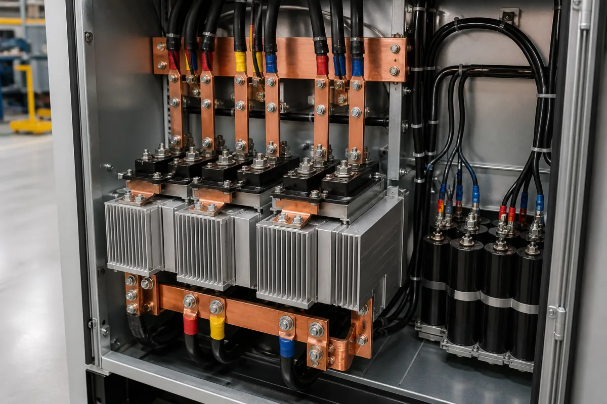
Rectifier circuit as a shared DC bus supply: a six-pulse diode or SCR bridge that converts three-phase AC once and feeds the DC links of a group of drives, sized by summed DC input current, precharge and bus capacitance
One rectifier for a group of drives · six-pulse diode or SCR bridges that feed a shared DC bus, who does the precharge, how much capacitance per amp the bus needs, and what paralleled bridges really deliver
In a machine with two or more motors, a stand-alone drive has its own input rectifier and DC link. A common-bus layout moves the rectifier out into one cabinet: a three-phase diode or SCR bridge, with fuses, busbars and where needed an extra capacitor bank, feeds DC to all of the drives' inverter sections, which can then exchange braking energy through the shared bus. The rectifier is chosen not by motor power but by the sum of the drives' DC input currents, and two questions decide whether it will survive start-up: which part of the system charges the capacitors gently, and whether the capacitance on the bus is spread evenly enough for the ripple current to be shared.
Three-phase rectifier circuits used as shared DC bus supplies for groups of drives: six-pulse diode and SCR bus supplies, their sizing on drive DC input currents, precharge arrangements, bus capacitance and capacitor banks, paralleled units and 12- or 18-pulse arrangements, and sharing or isolation diodes between drive buses. Packaged single- and three-phase bridges and their current and surge ratings are covered on the Rectifier bridge and Rectifier stack / bridge rectifier pages; high-current plating and electrolysis rectifiers on the Power supply unit (high-current DC rectifier cabinet) page; the rectifier, inverter and capacitors of induction melting furnaces on the Power supply system (induction melting furnace power system) page; drive input harmonics and chokes on the Variable frequency drive (VFD) in the control panel page; the inverter power stage with its own DC link on the Power electronics board page; rectifier heat sinks on the Rectifier heat sink and cooling system page.
CNFX editorial research · Sources checked October 13, 2026 · 3 sources
Sizing on the drives' DC input currents: 109.4 A on a 120 A diode supply, 773 A on a 1,000 A SCR supply
Rockwell defines a non-regenerative shared DC bus as a three-phase diode bridge, SCR bridge or a combination, converting AC to a fixed DC bus voltage with power flowing one way, from which one or more drives are fed. The bus supply is sized so that the sum of the connected drives' DC input currents, at their Normal Duty or Heavy Duty rating at 40 °C, does not exceed its continuous DC output rating. [1]
Rockwell notes that its SCR bus supply examples have no overload capability, while the drives' Normal Duty and Heavy Duty ratings include short overloads (110 % for 1 minute and 150 % for 3 seconds, or 150 % for 1 minute and 200 % for 3 seconds). [1] Editorial calculation: the example pairs 540 V DC with a 400 V supply and 650 V DC with 480 V, a ratio of 1.35 in both cases (540 / 400 = 1.35; 650 / 480 ≈ 1.35), which is the DC level a six-pulse bridge delivers from the line-to-line voltage. [1]
Bonitron's M3713 is a stand-alone six-pulse diode bridge built for this job, in 30 to 375 A sizes for 208–240, 460–480 and 575–600 V AC supplies, with or without SCR-bridge precharge (SC and DM versions). Up to three units can run in parallel, and pairs or triples with a phase-shifting transformer form 12- and 18-pulse supplies that Bonitron says let standard drives meet IEEE 519 with proper configuration. [2]
Rockwell example
DC bus
Drives connected
Current sum
Bus supply rating
AC input
Diode bus supply, Normal Duty
540 V
30 kW + 22 kW
61.9 + 47.5 = 109.4 A
120 A continuous
400 V
Diode bus supply, Heavy Duty
650 V
2 × 25 HP
2 × 42.9 = 85.8 A
120 A continuous
480 V
SCR bus supply, Normal Duty
540 V
3 × 110 kW + 1 × 45 kW
678 + 95 = 773 A
1,000 A maximum
400 V
SCR bus supply, Heavy Duty
650 V
3 × 125 HP
3 × 171 = 513 A
600 A maximum
480 V
List every drive on the bus with its DC input current at the duty rating that will be used, the DC bus voltage, the supply voltage, and any short-term overload the bus supply has to carry.
02
Who charges the capacitors: a diode bus supply has no precharge, so the drives must provide it
Precharge raises the DC bus voltage gradually so the filter capacitors charge in a controlled way. Rockwell's diode bus supply does not include precharge, so it may only feed drives that have their own precharge circuit; Rockwell warns never to connect drives without a controlled, current-limited precharge (certain Kinetix servo drives) to a diode bus supply, because the uncontrolled inrush damages them. [1]
Inside the drives, Rockwell describes three precharge forms: a resistor in series with the bus that a relay contact bypasses once the precharge level is reached (smaller frames); an SCR rectifier phase-advanced to limit inrush (larger AC-input frames); and resistors and diodes that charge the bus while the front-end SCRs are open, after which the SCRs take over. Drives without an internal precharge circuit must not be connected to an energised DC bus. [1]
Rockwell's SCR bus supply includes precharge, and drives without precharge may then be used only if power is always removed and restored to the whole system and no drive is isolated and reconnected to a live bus. For drives that do precharge, Rockwell recommends the 'Precharge Enable' digital input, coordinated by a PLC or by an auxiliary contact on each drive's disconnect, so that drives of different sizes have settled before precharge closes. [1]
On Bonitron's M3713 the precharge is a model choice: the SC version adds SCR-bridge precharge and the DM version has none; Bonitron's paralleling tables are given for the SC version. [2]
Arrangement
Precharge comes from
Rule stated
Diode bus supply (Rockwell)
Each connected drive
Only drives with their own precharge; never Kinetix 6000-series or 6200/6500, or Kinetix 7000 BM09–BM12 [1]
SCR bus supply (Rockwell)
The bus supply
Drives without precharge only if the whole system is powered down and up together [1]
M3713SC / M3713DM (Bonitron)
SC: SCR bridge in the supply; DM: none
Choose SC where the supply must charge the bus [2]
For each drive state whether it has its own precharge, whether any drive will be switched onto a live bus through a disconnect, and which unit (bus supply or drives) controls the precharge sequence.
03
Bus capacitance per amp: Rockwell's 40 µF/A target, a 110 µF minimum, and capacitor banks rated for 300 Hz ripple
All drives on a shared bus put their DC capacitors in parallel, so the bus ripple divides in proportion to each drive's capacitance. Rockwell targets a ratio of 40 µF or more per amp of drive DC input current; below that, an external capacitor bank equal to 40 µF × DC input amps minus the drive's own capacitance is added, as close as possible to the DC terminals of the largest drive. An SCR bus supply also needs at least 110 µF on the bus to commission, or its fault detection reads the bus as shorted. [1]
Editorial calculation: applying Rockwell's own formula to the Frame 6 row gives 40 × 272.1 − 9,200 = 1,684 µF, not the 1,648 µF printed in its table; the 700S rows check exactly (40 × 1,162 − 19,800 = 26,680 µF; 40 × 272 − 8,400 = 2,480 µF). Confirm the figure with the supplier before ordering a bank. [1]
Bonitron's M3612EC filter capacitor banks for shared buses show the scale involved: 28,000 µF at 450 V DC for 230–240 V AC systems and 7,000 µF at 900 V DC for 460–480 V AC, with maximum ripple current at 300 Hz of 385 A and 200 A at 45 °C, falling to 175 A and 90 A at 105 °C; end of life is defined as a 20 % capacitance loss or a 100 % ESR rise. [3] Paralleled rectifiers do not add up in full either: Bonitron lists 270 A for two 150 A M3713 units and 400 A for three. [2] Editorial calculation: 270 / (2 × 150) = 90 % and 400 / (3 × 150) ≈ 89 % of the summed single-unit rating. [2]
Where two or more drives keep their own input bridges and are tied only by their DC buses, circulating currents between the bridges are a risk; Bonitron lists its M3345CBM sharing diodes as preventing circulating currents in parallel bridges, for up to 6 connections, while allowing one regenerative or braking unit to serve more than one drive, and Rockwell sizes back-to-back diodes in shared AC/DC configurations at 125 % of the drive's DC input current. [2][1]
Rockwell example, 650 V DC
DC input current
Drive capacitance
µF/A
Extra capacitance stated
PowerFlex 750 Frame 8
599 A
23,700 µF
39.5
None
PowerFlex 750 Frame 6
272.1 A
9,200 µF
33.8
1,648 µF
PowerFlex 700S Frame 13
1,162 A
19,800 µF
17.0
26,680 µF
PowerFlex 700S Frame 6
272 A
8,400 µF
30.8
2,480 µF
Ask for the capacitance of each drive, the µF/A check against 40 µF/A, the rating, ripple current at 300 Hz and temperature, and end-of-life criteria of any added bank, and the DC fuses with diagnostic feedback recommended for it.
04
Bus supply details to send
Paste it into your enquiry below or into an email to a maker, then replace every bracket.
Supply: [AC voltage; frequency; short-circuit level]
DC bus: [voltage; diode or SCR bridge; 6, 12 or 18 pulse]
Drives: [each drive's DC input current and duty rating; capacitance; own precharge yes/no]
Precharge: [in the bus supply or in the drives; disconnects onto a live bus]
Capacitor bank: [µF; voltage; ripple current at 300 Hz; fusing]
Paralleling: [number of units; sharing or isolation diodes]
Explore company information and manufacturing capabilities, then discuss the scope of your project with a relevant supplier.
Share this page
Compiled and source-reviewed by the CNFX editorial team.
Each manufacturer above links to the page on that company's own website where the product is listed, with the date we checked it. How we source and review
· Page last updated 13 October 2026
Buyer questions
How is a shared DC bus rectifier sized?
Rockwell sums the DC input currents of the connected drives at their Normal or Heavy Duty rating at 40 °C; the total must not exceed the bus supply's continuous DC output, e.g. 109.4 A on a 120 A diode supply. [1]
Does a diode bus supply precharge the DC bus?
Rockwell's diode bus supply does not; precharge must come from the drives, and drives without controlled precharge must not be connected to it. Bonitron offers its M3713 with (SC) or without (DM) precharge. [1][2]
How much capacitance does a shared DC bus need?
Rockwell targets 40 µF or more per amp of drive DC input current, adds a capacitor bank where a drive falls short, and requires at least 110 µF to commission an SCR bus supply. [1]
Do paralleled rectifier units add their full current?
Not in Bonitron's tables: two 150 A M3713 units are listed at 270 A and three at 400 A. [2]
Sources and what still needs a direct check
Sources checked 2026-10-13. Three sources from two publishers: Rockwell Automation's application technique DRIVES-AT002H on PowerFlex drives sharing a DC bus, and two Bonitron documents, the M3713 three-phase power supply brochure and its DC bus filter product page.