Editorial Technical Reference

CIP Return Pump

This page explains how CIP Return Pump is classified within Food Manufacturing. Technical values and manufacturer relationships are research references; confirm the current specification and supplier evidence for each order.

Technical Definition & Core Assembly

A specialized pump designed to return cleaning solutions from the CIP system back to the central storage or drain after the cleaning cycle.
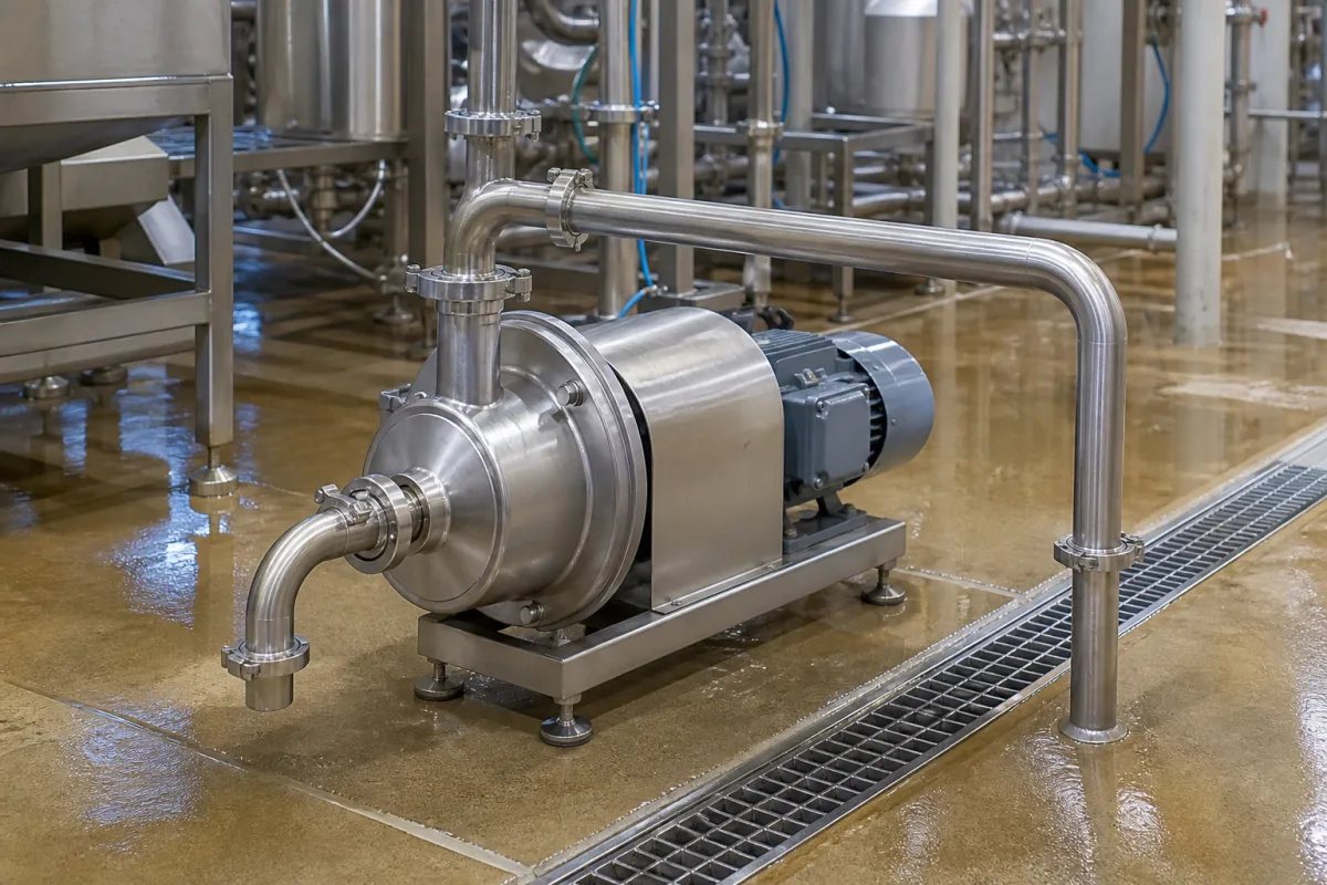
Representative product image. Confirm appearance and specifications with the manufacturer.

Product Specifications

Technical details and manufacturing context for CIP Return Pump

Definition
The CIP Return Pump is a critical component within a Clean-in-Place (CIP) system, responsible for actively drawing spent cleaning solutions, rinse water, and product residues from the equipment being cleaned. It ensures the complete evacuation of fluids from tanks, pipelines, and vessels, facilitating efficient cleaning cycles, preventing cross-contamination, and enabling the recovery or disposal of used solutions. Its performance directly impacts cleaning efficiency, water/chemical usage, and cycle time. This pump is typically a centrifugal or positive displacement type driven by an electric motor. It creates suction at its inlet, which is connected to the low point or drain of the equipment being cleaned, drawing the fluid through the system. The pump then pressurizes the fluid to overcome system pressure losses and transport it through return piping to a central collection tank, drain, or recovery system. Constructed with food-grade materials, the pump features stainless steel (AISI 304/316L) wetted parts and elastomers such as EPDM or Viton, ensuring compatibility with CIP chemicals and high temperatures. Key parameters include a flow rate of 15–60 m³/h, head of 20–50 m, operating pressure of 1.0–1.6 MPa, motor power of 2.2–11 kW, voltage of 380–480 V AC, frequency of 50–60 Hz, operating temperature of 20–95°C, max ambient temperature of 40°C, ingress protection of IP55–IP65, wetted material of 316L, seal type of SiC/SiC, and weight of 50–200 kg. These values are reference ranges and must be verified against the specific model and application. Standards such as ISO 9906, IEC 60034, IEC 60038, ISO 15761, IEC 60529, ASTM A240, and DIN 24960 are listed as procurement references, not as certifications. Always confirm model-specific values and standards with the legal manufacturer or supplier.
Working Principle
The CIP Return Pump operates by creating a pressure differential to move cleaning fluids. An electric motor drives the pump impeller or rotor, generating suction at the inlet. This suction draws spent cleaning solution, rinse water, and residues from the lowest point of the equipment being cleaned. The fluid enters the pump, where it gains kinetic energy and is then converted to pressure, allowing it to overcome friction losses in the return piping and elevation differences. The pressurized fluid is discharged through the outlet and transported to a central collection tank, drain, or recovery system. The pump must be sized to handle the required flow rate and head, considering the system's total dynamic head. Proper selection ensures efficient evacuation, prevents cross-contamination, and optimizes cleaning cycles.
Common Materials
Stainless Steel (AISI 304/316L), Food-Grade Elastomers (EPDM, Viton)
Technical Parameters
ParameterTypical rangeNotes & selection driver
Flow Rate15–60 m³/hSelect based on CIP tank volume and cycle timeISO 9906
Head20–50 mMust overcome pipe friction and elevationISO 9906
Motor Power2.2–11 kWMatch to flow and head requirementsIEC 60034
Voltage380–480 V ACThree-phase, 50/60 HzIEC 60038
Frequency50–60 HzMust match motor ratingIEC 60038
Operating Temperature20–95 °CFor CIP solutions up to 95°CISO 15761
Max Ambient Temperature40 °CHigher ambient may require deratingIEC 60034
Ingress ProtectionIP55–IP65IP65 for washdown areasIEC 60529
Wetted Material316LCorrosion-resistant for CIP chemicalsASTM A240
Seal TypeSiC/SiCSilicon carbide for durabilityDIN 24960
Weight50–200 kgDepends on pump size and motor

Ranges are indicative industry figures for RFQ preparation, not a supplier commitment. Confirm every value and standard with the legal manufacturer before ordering.

Components / BOM
  • Impeller
    Rotating component that transfers energy from the motor to the fluid, creating flow and pressure.
    Material: Stainless Steel
  • Casing / Volute Part
    Houses the impeller and converts the kinetic energy of the fluid into pressure.
    Material: Stainless Steel
  • Shaft Seal Part
    Prevents leakage along the drive shaft where it enters the pump casing. Common types include mechanical seals or gland packing.
    Material: Ceramic/Carbon (Seal Faces), Elastomers
  • Drive Motor
    Provides the rotational power to drive the pump impeller.
    Material: Various (Housing: Cast Iron/Aluminum, Windings: Copper)

Applied To / Applications

This component is essential for the following industrial systems and equipment:

Industrial Ecosystem & Supply Chain Structure

Complementary Systems
Downstream Applications
Specialized Tooling

Application Fit & Sizing Matrix

Operational Limits
pressure: Max 10 bar (145 psi) discharge pressure
flow rate: 5 to 200 m³/h (22 to 880 GPM)
temperature: +20°C to +95°C
slurry concentration: Up to 5% solids by weight
Media Compatibility
✓ Caustic cleaning solutions (NaOH/KOH) ✓ Acidic cleaning solutions (HNO₃/H₃PO₄) ✓ Hot water rinse (up to 95°C)
Unsuitable: Abrasive slurries with >5% solids or containing sharp particulates
Sizing Data Required
  • Required flow rate (m³/h or GPM)
  • System pressure drop (bar or psi)
  • Cleaning solution viscosity and temperature

Reliability & Engineering Risk Analysis

Failure Mode & Root Cause
Cavitation
Cause: Insufficient NPSH (Net Positive Suction Head) due to clogged inlet filters, excessive suction lift, or improper pump selection for the fluid temperature/vapor pressure
Mechanical seal failure
Cause: Dry running, chemical attack from CIP fluids, thermal stress from temperature cycling, or particulate buildup on seal faces
Maintenance Indicators
  • Unusual high-frequency vibration or rattling noise during operation (indicates cavitation or bearing wear)
  • Visible leakage at the seal housing or significant drop in discharge pressure despite normal motor current
Engineering Tips
  • Implement real-time NPSH monitoring and maintain inlet strainers; ensure proper pump selection for CIP fluid properties and temperature ranges
  • Establish a preventive maintenance schedule for seal inspection/flush systems and verify proper lubrication of bearings per manufacturer specifications

Indicative industry ranges for design and RFQ preparation. Confirm the exact figures and applicable standard with the manufacturer before specifying.

Compliance & Manufacturing Standards

Applicable Standards
ISO 2858: Centrifugal pumps - End-suction pumps (rating 16 bar) - Designation, nominal duty point and dimensions ANSI/ASME B73.1: Specification for Horizontal End Suction Centrifugal Pumps for Chemical Process DIN EN 22858: End-suction centrifugal pumps (rating 16 bar) - Nominal duty point, main dimensions

Quoted from the published standard.

Manufacturing Precision
  • Impeller diameter: +/-0.5% of nominal diameter
  • Shaft runout at mechanical seal face: ≤0.05mm
Quality Inspection
  • Hydrostatic pressure test: 1.5 times maximum working pressure for 30 minutes
  • Material verification test: PMI (Positive Material Identification) for wetted parts

Manufacturers of CIP Return Pump

Manufacturer profiles associated with CIP Return Pump.

Sourcing CIP Return Pump from China?
Tell us your specification and target quantity — we will match it against manufacturer records and come back with the factories that fit.
Request manufacturers We manufacture this

Manufacturer listings support early research and capability understanding. They are not certification, ranking, or transaction guarantees.

Technical documentation
Request current drawings, revision history, and a signed specification sheet.
Manufacturing capability
Verify equipment lists, process limits, capacity, and representative production evidence.
Inspection readiness
Confirm test methods, calibrated equipment, sampling plans, and traceable reports.
Supplier transparency
Check the legal entity, factory address, ownership, certifications, and direct contacts.

CNFX does not score or rank suppliers. Buyers must verify all claims and documents with the legal manufacturer before ordering.

Supply Chain Compatible Machinery & Devices

Automated Food Packaging Integrity Tester

Automated system for non-destructive testing of food package seals and integrity.

Explore Specs →
Control Panel

A centralized interface for monitoring and controlling industrial equipment and processes

Explore Specs →
High-Purity Sodium Nitrite Curing Salt

High-purity sodium nitrite curing salt is a critical raw material in industrial meat processing for preservation and color fixation.

Explore Specs →
Industrial Meat Grinder with Cryogenic Cooling

Industrial meat grinder with integrated cryogenic cooling system for temperature-controlled processing.

Explore Specs →

Frequently Asked Questions

What is the primary function of a CIP return pump?

The primary function is to actively draw spent cleaning solutions, rinse water, and product residues from the equipment being cleaned and transport them back to a central storage tank, drain, or recovery system, ensuring complete evacuation and efficient cleaning cycles.

What materials are typically used for the wetted parts?

Wetted parts are typically made of stainless steel (AISI 304/316L) and food-grade elastomers such as EPDM or Viton, providing corrosion resistance and compatibility with CIP chemicals and high temperatures.

How do I select the correct pump size?

Selection is based on required flow rate (15–60 m³/h), head (20–50 m), operating pressure (1.0–1.6 MPa), and motor power (2.2–11 kW). These values are reference ranges; consult the manufacturer for exact sizing based on your CIP tank volume, cycle time, and piping layout.

What standards are relevant for verification?

Relevant standards include ISO 9906 for hydraulic performance, IEC 60034 for motors, IEC 60038 for voltage/frequency, ISO 15761 for temperature, IEC 60529 for ingress protection, ASTM A240 for material, and DIN 24960 for seals. These are references, not certifications; verify compliance with the supplier.

Data Basis

Editorial classification, named public sources where available, and source-reviewed manufacturer records.

Preliminary Technical Classification
This page supports structured research, RFQ preparation, and supplier evaluation. It does not replace buyer-led supplier qualification, standards review, or technical approval.
Buyer enquiry

Request manufacturing insight for CIP Return Pump

Ask for use case, specification boundaries, supplier type, and RFQ preparation information for this product.

Where it goes
Straight to the CNFX editorial desk, and to the manufacturer if this product is linked to a claimed profile. Nothing is broadcast to a supplier list.
Your details stay here
We do not sell or rent enquiry data, and we do not add you to a mailing list. Used only to answer this request.
No commission, no middleman
CNFX is a directory. We take no cut of any order and never negotiate on a supplier's behalf.
What we don't claim
A listing is not an endorsement. Qualify every supplier and verify every figure yourself before ordering.

Your business information is used only to process this request.

Thank you! Your message has been sent. We'll respond within 1–3 business days.
Sorry, we couldn't send your message. Please try again, or email us at contact@cnfx.com.

Need to Manufacture CIP Return Pump?

Compare manufacturer profiles with relevant product and process capability.

Previous Product
Tubular Heat Exchanger
Last Product
Get QuotesChat