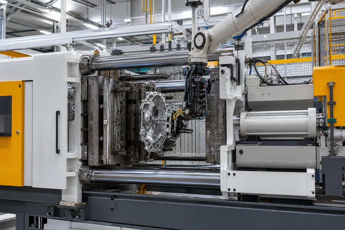
HPDC machines · Cavity fill time, gate velocity by alloy, gate area, die wear above 40 m/s, separating force and clamping force
A high-pressure die casting machine injects molten aluminium, magnesium or zinc through a shot sleeve or gooseneck into a steel die at high speed, intensifies the pressure as the casting solidifies, then opens the die and ejects the part. Ask three things first: what fill time and gate velocity your casting needs and whether the shot end can deliver them, how much clamping force the projected area and cavity pressure demand, and how the cell extracts, sprays and trims each part.
Cold-chamber and hot-chamber high-pressure die casting machines and cells for aluminium, magnesium and zinc alloys, with shot end, clamping unit, extraction and die spraying. Low-pressure, gravity and squeeze casting machines, dies and trim presses sold alone are outside this page.
CNFX editorial research · Sources checked October 11, 2026 · 4 sources
Majernikova and co-authors (MM Science Journal, December 2024) review gating design for high-pressure die casting. They state that too short a fill time leaves gases in the cavity and raises porosity, while too long a fill time lets the flow front cool so streams fail to join. Czech standard CSN 22 8601 recommends fill times by predominant wall thickness, for example 0.01–0.03 s below 1.5 mm, 0.04–0.09 s below 2.5 mm and 0.08–0.30 s below 6.3 mm. [1]
They give NADCA's fill-time relation t = K × (T_G − T_LIK + S × Z) / (T_LIK − T_D) × h_CH, with K = 0.0346 s/mm for H13 or H21 die steel with aluminium, permissible solidification S of 20–50% for 2–3 mm aluminium walls, and Z = 4.8 °C/% for hypoeutectic AlSi alloys such as 380. Recommended gate velocities are 20–60 m/s for aluminium (15–30 m/s with vacuum), 40–90 m/s for magnesium and 20–30 m/s for zinc; machines can reach 100 m/s, but moulds begin to degrade at about 40 m/s. [1]
Editorial calculation: with assumed gate temperature 650 °C, liquidus 595 °C, die 230 °C, S = 30% and a 2.5 mm wall, t = 0.0346 × (650 − 595 + 30 × 4.8) ÷ (595 − 230) × 2.5 ≈ 0.047 s, inside the CSN range. Filling 300 cm³ of casting and overflows in 0.047 s at 40 m/s needs a gate area of about 300 ÷ (40 × 0.047) ≈ 159 mm². Ask the machine supplier to confirm its shot end reaches the needed flow and pressure. [1]
Give the supplier the alloy, casting drawing with projected area and wall thickness, shot weight with runners and overflows, target fill time and gate velocity, required intensification pressure, die size and height, cycle time, extraction, spraying and trimming automation, vacuum assistance, and safety and power requirements.
02
Size the clamping force against the separating force
The clamping unit must hold the die closed against the separating force, the cavity pressure acting on the projected area of the casting plus runners and overflows in the parting plane. The same paper describes the injection as pressing liquid metal into the cavity at high speed and pressure through a complex motion system, naming porosity as the main defect. [1]
Editorial calculation: at an assumed intensification pressure of 60 MPa on a projected area of 500 cm² (0.05 m²), the separating force is 60 × 10⁶ × 0.05 = 3,000 kN; with an assumed 20% margin the machine needs about 3,600 kN of locking force. Use the cavity pressure your casting quality needs and the full projected area, then ask suppliers for the locking force, tie-bar spacing and die height that fit your die.
Editorial note: the supplier listed below makes cold-chamber machines; ask for the shot-end performance diagram (pressure against flow) of the offered size so the fill time and gate area above can be checked against it.
03
Check the casting area each plunger diameter allows
HMT Machine Tools' specification page for its H 250D horizontal cold-chamber machine shows how one clamp size serves different castings by changing the plunger. It lists 250 tonnes of locking force, an adjustable injection force of 38 tonnes with intensifier, 500 × 550 mm between tie bars, die height 225–750 mm and a 350 mm injection plunger stroke, with the 60 mm plunger as the standard shot sleeve. [4]
Editorial calculation: 38 tonnes on the 60 mm plunger (28.3 cm²) gives 38,000 ÷ 28.3 ≈ 1,343 kg/cm², matching the listed 1,345 kg/cm², and 250 tonnes ÷ 1,345 kg/cm² ≈ 186 cm², matching the 185 cm² casting area. In SI units 1,345 kg/cm² is about 132 MPa and 250 tonnes about 2,450 kN. [4]
The same page lists a free cycle time of 5.5 s, a 22.4 kW motor, a 550 litre oil tank, a machine weight of 10 tonnes and a machine area of 5.9 × 1.6 m. Ask for these values for the size you are offered so the foundation, power supply and cell layout can be planned. [4]
Plunger diameter (mm)
Shot capacity, aluminium (kg)
Max. injection pressure (kg/cm²) → nominal casting area (cm²)
40
0.8
3,025 → 82
50
1.2
1,935 → 129
60 (standard sleeve)
1.8
1,345 → 185
70
2.4
985 → 253
85
3.6
670 → 373
04
Read the machine data sheet: locking force, shot end and casting area
IDRA's XPRESS cold-chamber catalogue tabulates, for each size, clamping force, stroke, die height, platen and tie-bar dimensions, ejection force, injection force and stroke, plunger diameters, shot weight, intensified casting pressure by plunger, the casting area that pressure allows and a maximum casting area at 400 bar, with a working pressure of 160 bar. [2]
Shibaura Machine's DC-J series lists, for the DC250J, 2,500 kN die locking force, 580 × 580 mm tie-bar spacing, 300–600 mm die height and 360 mm die stroke, with injection speed of 0.1–7.0 m/s (SC), 0.05–8.0 m/s (MS) and 0.05–13.0 m/s (MH) depending on the shot-end variant. [3]
Editorial calculation: 3,000 kN ÷ 400 bar (40 MPa) = 0.075 m² = 750 cm², matching IDRA's maximum casting area; 419 kN on a 70 mm plunger (3,848 mm²) gives about 1,089 bar and on a 50 mm plunger (1,963 mm²) about 2,134 bar, matching the 1,050–2,100 bar range, so a smaller plunger raises metal pressure and lowers shot weight. For the 500 cm² example above at 600 bar, the 300 S covers 3,000 kN ÷ 60 MPa = 500 cm² with no margin, so the 3,600 kN with margin points to the 4,360 kN size. [2]
IDRA XPRESS
300 S
420
560
700
Clamping force (kN)
3,000
4,360
5,850
7,500
Space between tie bars (mm)
560 × 560
669 × 669
760 × 760
860 × 860
Die height (mm)
250–650
250–700
300–800
400–900
Injection force (kN, 0 bar back pressure)
419
457
531
615
Plunger diameter (mm)
50–70
60–80
70–90
80–100
Shot weight, Al (kg)
1.6–3.2
2.6–4.7
4.3–7.1
6.1–9.5
Casting pressure (bar)
2,100–1,050
1,600–900
1,350–800
1,200–750
Casting area (cm²)
140–285
270–480
430–730
625–1,000
Max. casting area at 400 bar (cm²)
750
1,090
1,463
1,875
Ask for the full data sheet and shot-end performance (P–Q) diagram for the offered plunger, plus injection speed range with and without metal, and check casting area at your intensification pressure.
05
Cold-chamber high-pressure die casting machines from the listed supplier
Listings include cold-chamber high-pressure die casting machines.
06
Shot end, shot sleeve and plunger, clamping unit, die, hydraulic unit and cell automation
The shot sleeve and plunger are the part to choose per casting: on HMT's H 250D the same 250-tonne clamp covers 82 cm² of casting area with a 40 mm plunger and 373 cm² with an 85 mm one. [4]
Clamping force, casting pressure, injection speed, shot weight, platen and die height for a machine quotation
Clamping force follows from cavity pressure and projected area, and the published machines span 2,500 to 7,500 kN; the fill time and gate velocity worked out above decide which shot end and plunger the offer needs. [2][3][1]
Field
What it means and published values
Ask the supplier for
Clamping force (kN)
Must exceed cavity pressure × projected area; 2,500–7,500 kN in the tables cited. [2][3]
Locking force.
Injection pressure (MPa)
Intensified casting pressure depends on plunger, e.g. 1,050–2,100 bar. [2]
Static and intensified pressure.
Injection speed (m/s)
0.05–13.0 m/s by shot-end variant on one machine. [3]
Speed with and without metal.
Shot weight (kg)
Casting, runners, overflows; 1.6–9.5 kg Al across one range. [2]
Maximum shot.
Platen size (mm)
Fits the die; 860 × 860 mm platen, 560 × 560 mm between tie bars on one 3,000 kN machine. [2]
1 company lists this product among what they make. Company figures are quoted from each
company's own website; every card states where the relationship came from.
Explore company information and manufacturing capabilities, then discuss the scope of your project with a relevant supplier.
Share this page
Compiled and source-reviewed by the CNFX editorial team.
Each manufacturer above links to the page on that company's own website where the product is listed, with the date we checked it. How we source and review
· Page last updated 13 October 2026
Buyer questions
How fast should an aluminium die casting fill?
CSN 22 8601 recommends fill times by wall thickness, for example 0.04–0.09 s for walls under 2.5 mm; NADCA's formula refines this. [1]
What gate velocity is used for aluminium die casting?
For aluminium, 20–60 m/s in normal casting and 15–30 m/s in vacuum casting (ČSN 22 8601, as tabled in the MM Science Journal paper); moulds begin to degrade at about 40 m/s. [1]
Why does fill time matter?
Too short traps gas and raises porosity; too long lets the flow front cool so streams fail to join. [1]
How does plunger size affect a die casting machine?
For the same injection force a smaller plunger gives higher metal pressure and a smaller shot: 419 kN gives about 2,100 bar on a 50 mm plunger and 1,050 bar on 70 mm. [2]
How fast can the shot end inject?
One 2,500 kN machine lists 0.1–7.0, 0.05–8.0 or 0.05–13.0 m/s depending on the shot-end variant. [3]
Why does a die casting machine list more than one casting area?
With a fixed injection force, a larger plunger gives a bigger shot at lower metal pressure, and the lower pressure lets the same locking force hold a larger projected area. HMT Machine Tools' H 250D page lists 82 cm² at 3,025 kg/cm² on a 40 mm plunger and 373 cm² at 670 kg/cm² on an 85 mm plunger. [4]
Sources and what still needs a direct check
Sources checked 2026-10-11. The MM Science Journal paper is a peer-reviewed review of gating design that cites NADCA and CSN 22 8601; IDRA, Shibaura Machine and HMT Machine Tools publish data for their own machines; the clamping calculation uses assumed pressures. Confirm machine sizing with the supplier and your die designer.