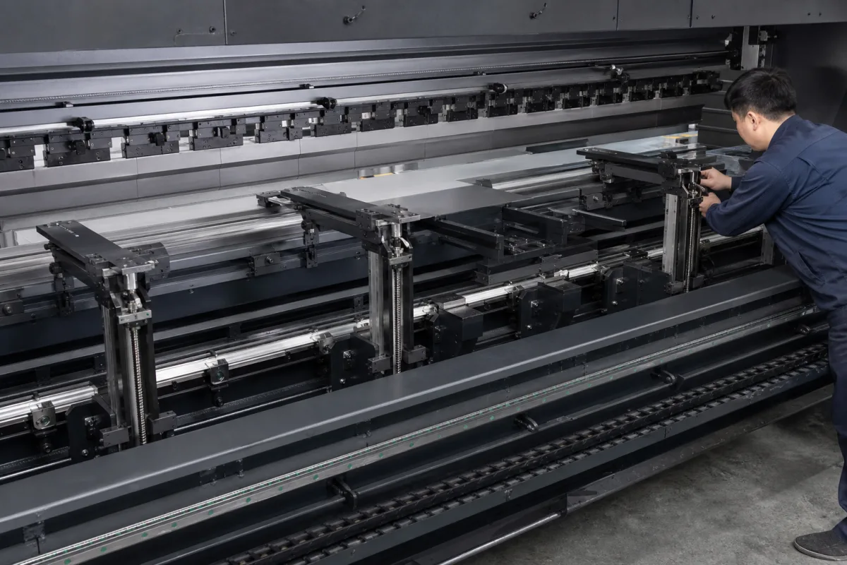
Press brake back gauges · Axes and per-axis accuracy, retract and finger-to-die collision zones
A press brake back gauge is the CNC-driven set of stop fingers behind the die that positions sheet metal before each bend, so that the bend line lands at the programmed distance from the sheet edge. Ask three things first: which axes are motorised and what accuracy each axis holds, how and when the fingers retract while the punch grips the sheet, and how the control keeps the fingers clear of the die when axes move.
CNC back gauges for press brakes, supplied with a new machine or as a retrofit, including the beam, drives, fingers and their control functions. Complete press brakes, front sheet supports and shear back gauges are outside this page.
CNFX editorial research · Sources checked October 12, 2026 · 4 sources
Cincinnati's 5-axis back gauge retrofit gives independent control of two front-to-back axes (X1, X2), two left-to-right axes (Z1, Z2) and one up-down axis (R). It lists a horizontal range of 0–24 in at 1,200 IPM with ±0.001 in positioning accuracy and repeatability; a vertical (R) range of 8 in at 300 IPM with ±0.005 in accuracy and ±0.003 in repeatability; and lateral (Z) positioning at 3,000 IPM with ±0.015 in accuracy and repeatability. [1]
Selmach explains that automated back gauges arrived in the 1970s moving on the X axis only, and that today each axis, up to six, can have its own DC motor travelling on ballscrew spindles, with axis sets such as X, X-R and X-R-Z1-Z2. Its X-axis back gauge has a 1,000 mm range and a maximum travel speed of 330 mm/s. [2] Cincinnati states that its gauge uses closed-loop servo drives and is designed for material up to 1/4 in thick that one or two operators can handle, with thicker parts up to 150 lb processed with reasonable care. [1]
Editorial calculation: 1,200 IPM is 1,200 × 25.4 / 60 = 508 mm/s, and ±0.001 in is ±0.025 mm, ±0.005 in is ±0.127 mm and ±0.015 in is ±0.381 mm. Accuracy is quoted per axis, so the lateral (Z) and height (R) figures are looser than the X figure in the same listing; ask for each axis separately rather than one number for the gauge. [1]
Give the supplier the press brake make, model, length and control, the axes required, X stroke and the longest flange to gauge, the thickest and heaviest part, the finger types and number, required accuracy and repeatability per axis, guarding, and the control's gauge and collision functions.
02
Plan retract and finger-to-die clearance
Delem's DA-66T reference manual (version V0311) states that the back gauge retract starts when the beam is pinching the sheet. A 'wait for retract' setting decides whether the beam keeps moving through the clamping point while the gauge retracts, or stops there until the retract is complete and then moves on. [3]
The same manual computes a minimum X position for each die where an R axis is fitted, to prevent finger-to-die collision: X-safe = FS + ½V, where FS is the flat section behind the V groove and V the opening, plus 0.5 mm extra. The die safety zone is SZ = X-safe + SD, where SD is a safety distance defined by the machine supplier. When the gauge must move to a new Z position from inside that zone, it first moves to an 'intermediate X'; when X must move inside the zone, R can first go to an 'intermediate R'. [3]
Delem also describes 'lay-on' levels for fingers on a moving R axis, which change the X and R axis positions so the sheet rests on a different finger step while the gauge position stays the same, and a per-line precision option that chooses the back stop position for the highest accuracy or for a closing dimension, at the cost of longer production time. [3]
Editorial calculation: with an assumed die of V = 16 mm and FS = 5 mm, X-safe = 5 + 8 + 0.5 = 13.5 mm, so flanges shorter than that cannot be gauged against fingers that drop to die height without changing die or finger level. The die values are an example; use your tooling drawings. [3]
03
Match the back gauge configuration to the press brake
Salvagnini's B3 electric press brake page offers its back gauges in six different types, from 4 to 9 axes, and states that all axes slide on linear guides. The same page lists the machine data the back gauge must work within: table lengths of 2,040 to 4,250 mm across the 80/2000 to 170/4250 models, throat depths of 350 to 520 mm, a maximum approach and return speed of 250 mm/s (180 mm/s on the 170/3000XL) and a bending speed of 15 mm/s. Its optional safety system, a laser transmitter with an HD camera, can reduce the speed-change position to as little as 2 mm from the sheet. [4]
Compare the axis count and travel offered here with the 5-axis retrofit figures, the finger and axis guidance, and the controller retract settings above. [1][2][3]
Editorial calculation: a 4-axis and a 9-axis configuration differ by five independently driven axes; at 250 mm/s the ram covers its 300 mm maximum stroke on the 80/2000 in about 1.2 s, the time window in which the gauge must reposition between bends.
B3 model (Salvagnini)
Table length (mm)
Throat depth (mm)
Approach/return speed (mm/s)
80/2000
2,040
350
250
100/3000
3,060
435
250
135/4250
4,250
435
250
170/3000XL
3,060
520
180
State the axis count you need (for example X1, X2, R1, R2, Z1, Z2), the travel and speed of each axis, and whether the gauge runs on linear guides, and ask how these match the throat depth and table length of the press brake it will be fitted to.
04
Press brake builders offering multi-axis gauges
The listings are press brake builders offering multi-axis back gauges on their own machines; ask whether a gauge can be supplied as a retrofit and which control it runs on.
Stroke, speed and accuracy per axis, then force, drives and guides
Cincinnati, Selmach and Salvagnini figures fill the stroke, speed, accuracy and axis-count rows; finger force, motor, enclosure and guide rows have no published value and must come from the supplier.
Wuxi Shenchong lists a back gauge with movable, liftable fingers in 4+1, 6+1 and 8+1 axis versions on its hybrid servo press brake; the other listings offer back gauges as press brake options or upgrades.
Wuxi Shenchong Forging Machine Co., Ltd.
Manufacturing site to be confirmed for the order
Lists a back gauge with movable, liftable fingers in 4+1, 6+1 and 8+1 axis versions on its hybrid servo press brake.
Explore company information and manufacturing capabilities, then discuss the scope of your project with a relevant supplier.
Share this page
Compiled and source-reviewed by the CNFX editorial team.
Each manufacturer above links to the page on that company's own website where the product is listed, with the date we checked it. How we source and review
· Page last updated 13 October 2026
Buyer questions
What do X, R and Z mean on a back gauge?
In Cincinnati's 5-axis gauge, X1 and X2 move the fingers front to back, Z1 and Z2 left to right, and R up and down. [1]
How accurate is a CNC back gauge?
It differs by axis: Cincinnati lists ±0.001 in on X, ±0.005 in on R and ±0.015 in on Z for its retrofit gauge. [1]
When does the back gauge retract?
Delem's DA-66T manual says the retract starts when the beam pinches the sheet; a setting decides whether the beam waits for it. [3]
How many axes can a back gauge have?
Selmach describes gauges from X only up to heavy-duty six-axis designs, each axis on its own motor and ballscrew. [2]
How many axes can a press brake back gauge have?
Salvagnini offers its B3 back gauges in six types from 4 to 9 axes, all sliding on linear guides; Cincinnati's retrofit is a 5-axis design. [4][1]
Sources and what still needs a direct check
Sources checked 2026-10-12. Cincinnati and Selmach are press brake makers describing their own back gauges; Delem's manual describes how its controller drives a back gauge. Figures are those makers' published values, not industry limits.