Editorial Technical Reference

Climate Control System

This page explains how Climate Control System is classified within Machinery and Equipment Manufacturing. Technical values and manufacturer relationships are research references; confirm the current specification and supplier evidence for each order.

Technical Definition & Core Assembly

A system within the Control Cabin that regulates temperature, humidity, and air quality to maintain optimal environmental conditions for operators and equipment.
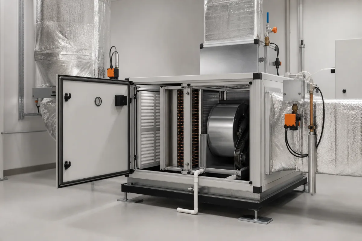
Climate Control System in a manufacturing environment
Representative product image. Confirm appearance and specifications with the manufacturer.

Product Specifications

Technical details and manufacturing context for Climate Control System

Definition
The Climate Control System is an integral subsystem of the Control Cabin, responsible for creating and maintaining a stable, comfortable, and safe internal environment. It manages thermal loads from electronic equipment and personnel, controls humidity to prevent condensation and static discharge, and ensures adequate ventilation and air filtration. Its operation is critical for the reliability of sensitive control instruments and the well-being of human operators, directly impacting the overall safety and efficiency of the industrial process.

This component is designed for machinery and equipment manufacturing applications, typically installed in control cabins of industrial machines. It operates on a closed-loop control principle, using sensors to monitor cabin conditions and actuators to adjust them. The system includes heating and cooling capabilities, humidity control, and air circulation, with components such as compressors, heat exchangers, fans, and ductwork.

Key parameters to consider when selecting a system include cooling capacity (2.5–12.5 kW), heating capacity (2–10 kW), airflow rate (800–3000 m³/h), temperature control accuracy (±1 °C), humidity control range (30–70 % RH), operating temperature range (-40–85 °C), supply voltage (24 V DC ±10%), power consumption (1.5–6 kW), IP rating (IP54–IP65 per IEC 60529), refrigerant type (R134a per ISO 817), compressor type (scroll), weight (45–120 kg), and dimensions (800×600×400 to 1200×800×600 mm). These values are reference ranges and must be verified for the specific model and application.

Materials used include galvanized steel for ductwork, copper for refrigeration lines, aluminum for heat exchangers, plastic polymers for housing and fittings, and electronic components for control. The system is designed to fit within the cabin envelope and must be integrated with the cabin's structural and electrical interfaces.

For procurement, verify model-specific performance data, compliance with applicable standards, and compatibility with the cabin's heat load and environmental conditions. Always confirm specifications with the legal manufacturer or supplier before purchase.
Working Principle
The system operates on a closed-loop control principle. Sensors (e.g., thermostats, hygrometers) continuously monitor cabin temperature and humidity. This data is fed to a controller, which compares it against preset parameters. Based on the deviation, the controller activates actuators: heating elements or a heat pump for warming, a refrigeration cycle (compressor, evaporator, condenser) for cooling, humidifiers or dehumidifiers for moisture control, and fans/blowers for air circulation and filtration. The conditioned air is then distributed throughout the cabin via ductwork.
Common Materials
Galvanized Steel (ductwork), Copper (refrigeration lines), Aluminum (heat exchangers), Plastic Polymers (housing, fittings), Electronic Components (PCBs, sensors)
Technical Parameters
ParameterTypical rangeNotes & selection driver
Cooling Capacity2.5–12.5 kWMatches cabin heat load
Heating Capacity2–10 kWFor cold climate operation
Airflow Rate800–3000 m³/hEnsures air exchange rate
Temperature Control Accuracy±1 °CMaintains operator comfort
Humidity Control Range30–70 % RHPrevents condensation and corrosion
Operating Temperature Range-40–85 °CFull environmental envelope
Supply Voltage24 ±10% V DCCommon in mobile equipment
Power Consumption1.5–6 kWAt full load
IP RatingIP54–IP65Dust and water resistanceIEC 60529
Refrigerant TypeR134aEnvironmentally friendlyISO 817
Compressor TypeScrollHigh efficiency and low noise
Weight45–120 kgAffects mounting structure
Dimensions (L×W×H)800×600×400–1200×800×600 mmFit into cabin envelope

Ranges are indicative industry figures for RFQ preparation, not a supplier commitment. Confirm every value and standard with the legal manufacturer before ordering.

Components / BOM
  • Compressor
    Compresses the refrigerant gas, raising its pressure and temperature to initiate the cooling cycle.
    Material: Cast Iron/Steel Alloy
  • Evaporator Coil
    Absorbs heat from the cabin air as liquid refrigerant evaporates, cooling the air.
    Material: Copper/Aluminum
  • Condenser Coil Part
    Releases absorbed heat to the outside environment as refrigerant condenses back to liquid.
    Material: Copper/Aluminum
  • Expansion Valve
    Regulates the flow of refrigerant into the evaporator, causing a pressure drop that facilitates cooling.
    Material: Brass/Stainless Steel
  • Blower Fan & Motor
    Circulates cabin air across the evaporator coil and distributes conditioned air through ducts.
    Material: Plastic/Steel (housing), Copper Windings (motor)
  • Air Filter Part
    Removes dust, particulates, and contaminants from the circulated air.
    Material: Synthetic Fiber/Pleated Paper
  • Control Unit / Thermostat
    The user interface and logic controller that monitors sensors and commands system operation to maintain setpoints.
    Material: Plastic (housing), Electronic Components
  • Ductwork
    Network of channels that distributes conditioned air to different zones within the Control Cabin.
    Material: Galvanized Steel/Insulated Aluminum
  • Heating Element
    Warms the cabin air when the setpoint is above ambient.
  • Humidifier / Dehumidifier
    Adds or removes moisture to hold the cabin humidity at setpoint.
  • Humidity Sensor (Hygrometer)
    Measures cabin humidity and feeds it back to the controller.

Applied To / Applications

This component is essential for the following industrial systems and equipment:

Industrial Ecosystem & Supply Chain Structure

Complementary Systems
Downstream Applications
Specialized Tooling

Application Fit & Sizing Matrix

Operational Limits
pressure: 0-500 Pa differential pressure capability
flow rate: 100-2000 m³/h adjustable airflow
air quality: PM2.5 < 15 μg/m³, CO2 < 1000 ppm maintained
temperature: -40°C to +85°C
humidity control: 20-80% RH, ±5% control accuracy
Media Compatibility
✓ clean room environments ✓ electronic equipment rooms ✓ pharmaceutical manufacturing areas
Unsuitable: high particulate environments (e.g., cement plants, foundries)
Sizing Data Required
  • cabin volume (m³)
  • heat load from equipment (kW)
  • required air changes per hour (ACH)

Reliability & Engineering Risk Analysis

Failure Mode & Root Cause
Refrigerant Leakage
Cause: Corrosion of copper tubing due to moisture ingress, vibration-induced fatigue at joints, or improper brazing during installation leading to micro-fractures.
Compressor Seizure
Cause: Insufficient lubrication from oil breakdown or contamination, refrigerant floodback washing oil from bearings, or electrical issues causing overheating and thermal expansion.
Maintenance Indicators
  • Unusual grinding or knocking sounds from the compressor unit
  • Visible ice buildup on evaporator coils or refrigerant lines
Engineering Tips
  • Implement quarterly infrared thermography scans to detect abnormal temperature differentials in electrical components and refrigerant lines before failures occur.
  • Install vibration monitoring sensors on compressors and fans with automated alerts for amplitude changes exceeding 10% baseline, indicating bearing wear or imbalance.

Indicative industry ranges for design and RFQ preparation. Confirm the exact figures and applicable standard with the manufacturer before specifying.

Compliance & Manufacturing Standards

Applicable Standards
ISO 16890: Air filters for general ventilation ANSI/ASHRAE 62.1: Ventilation for acceptable indoor air quality CE Marking: Directive 2014/35/EU (Low Voltage Directive)

Quoted from the published standard.

Manufacturing Precision
  • Refrigerant charge accuracy: +/-5% of specified mass
  • Airflow rate: +/-10% of rated capacity at design conditions
Quality Inspection
  • Leak testing (pressure decay or helium mass spectrometry)
  • Performance verification test (temperature/humidity control accuracy)

Manufacturers of Climate Control System

2 companies list this product among what they make. Company figures are quoted from each company's own website; every card states where the relationship came from.

Gloreen Electrical Equipments Co., Ltd.
Guangzhou, Guangdong, CN
Also makes: Thermostat, Control System, Fan / Blower and 2 more
Listed on the company's own website · profile compiled by CNFX from public sources
Listed there as: “CLIMATE CONTROL SYSTEM”
View source page ↗ gloreen.com · checked 2026-09-10
JIECANG
Zhejiang, CN
Listed on the company's own website · profile compiled by CNFX from public sources
Listed there as: “Climate Control System”
View source page ↗ jiecang.com · checked 2026-09-12

Manufacturer listings support early research and capability understanding. They are not certification, ranking, or transaction guarantees.

Share this page
Technical documentation
Request current drawings, revision history, and a signed specification sheet.
Manufacturing capability
Verify equipment lists, process limits, capacity, and representative production evidence.
Inspection readiness
Confirm test methods, calibrated equipment, sampling plans, and traceable reports.
Supplier transparency
Check the legal entity, factory address, ownership, certifications, and direct contacts.

CNFX does not score or rank suppliers. Buyers must verify all claims and documents with the legal manufacturer before ordering.

Supply Chain Compatible Machinery & Devices

Hydraulic Press

Industrial machine using hydraulic pressure to compress, form, or assemble materials

Explore Specs →
Heavy-Duty CNC Plasma Cutting Machine

The Heavy-Duty CNC Plasma Cutting Machine is a standalone industrial device designed for cutting conductive metals such as steel, stainless steel, aluminum, and copper alloys.

Explore Specs →
Automated Powder Coating System

Integrated industrial system for applying dry powder coatings to metal substrates.

Explore Specs →
Centrifugal Pump Impeller

The centrifugal pump impeller is a critical rotating component that converts mechanical energy from the motor into kinetic energy in fluid systems.

Explore Specs →

Frequently Asked Questions

What is the typical cooling capacity range?

The cooling capacity ranges from 2.5 to 12.5 kW, depending on the model. This should match the cabin's heat load, which must be calculated for the specific equipment and operator occupancy.

What power supply is required?

The system typically operates on 24 V DC with a tolerance of ±10%. Verify the exact voltage and current requirements with the manufacturer for the specific model.

What is the operating temperature range?

The system is designed to operate in ambient temperatures from -40°C to 85°C. However, performance may vary at extremes, so confirm the actual operating envelope for your application.

What standards apply to this system?

The IP rating is specified per IEC 60529, and the refrigerant type is per ISO 817. These standards are references for verification; compliance must be confirmed with the manufacturer.

Data Basis

Editorial classification, named public sources where available, and source-reviewed manufacturer records.

Preliminary Technical Classification
This page supports structured research, RFQ preparation, and supplier evaluation. It does not replace buyer-led supplier qualification, standards review, or technical approval.
Buyer enquiry

Request manufacturing insight for Climate Control System

Ask for use case, specification boundaries, supplier type, and RFQ preparation information for this product.

Where it goes
Straight to the CNFX editorial desk, and to the manufacturer if this product is linked to a claimed profile. Nothing is broadcast to a supplier list.
Your details stay here
We do not sell or rent enquiry data, and we do not add you to a mailing list. Used only to answer this request.
No commission, no middleman
CNFX is a directory. We take no cut of any order and never negotiate on a supplier's behalf.
What we don't claim
A listing is not an endorsement. Qualify every supplier and verify every figure yourself before ordering.

Your business information is used only to process this request.

Thank you! Your message has been sent. We'll respond within 1–3 business days.
Sorry, we couldn't send your message. Please try again, or email us at [email protected].

Need to Manufacture Climate Control System?

Compare manufacturer profiles with relevant product and process capability.

Previous Product
Cleaning-in-Place (CIP) System
Next Product
Closure Mechanism
Get QuotesChat