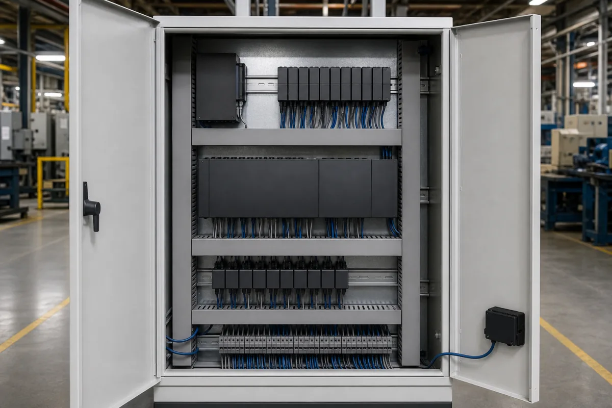
Mass flow controller power supply, readout and setpoint electronics: the secondary electronics that run a bank of MFCs
The separate box or rack that powers a bank of mass flow controllers, sends each its setpoint and shows what it reads · sized by supply rails and current per channel, and matched to the controllers by signal range, connector and gas correction
A mass flow controller is only the sensor, valve and control circuit in the gas line. On a test bench, a furnace or a small gas panel it still needs DC power, a setpoint for each channel, a display of the measured flow and, if a computer is involved, a serial or fieldbus link. Those functions sit in separate electronics: a bench or panel box for one to four channels or a 19-inch rack unit, which flow-controller makers call power supply and readout units or secondary electronics.
Power supply, readout and setpoint units (secondary electronics) for thermal, Coriolis and pressure-based mass flow controllers and meters: supply rails and current per channel, number of channels, analog setpoint and output ranges, gas correction factors, valve override, serial and fieldbus links, housings and operating limits. The flow controllers themselves are covered on the Mass flow controller (MFC) page and pressure-based types on the Precision flow controller of the pressure-based type page; electric-actuator liquid flow control on the Liquid flow controller with electric valve actuator page.
CNFX editorial research · Sources checked October 13, 2026 · 3 sources
Powering a bank of MFCs: ±15 V at 1.0 A shared by four channels, 400 mA per channel, or +24 V at 1.25 A
The supply rails and the current available per channel decide which controllers a unit can run and how many at once; the three units below state them differently.
Editorial calculation: four Brooks channels each drawing their 400 mA maximum need 1.6 A, inside the 2.0 A of the +15 V output; the MKS 247D's 1.0 A shared equally over four channels leaves 250 mA each, so the controllers' own current draw at full valve opening has to be checked against the supply, not only the channel count. [2][1] For the E-8000, 24 V × 1.25 A = 30 W, matching its stated power. [3]
The rails also decide compatibility: MKS lists the 247D for its own ±15 V controllers (for example 1179, 1479 and 1559 series), while the Brooks 0254 is ordered with either a ±15 Vdc or a +24 Vdc supply output, and the E-8000 supplies +24 Vdc to Bronkhorst digital instruments. [1][2][3]
Unit
Channels
Supply output to the MFCs
Mains input and own draw
Operating temperature
MKS 247D (discontinued; MKS names the PSR4A as replacement)
List each MFC's supply voltage and maximum current, the number of channels now and later, the mains supply and the ambient temperature where the unit will sit.
02
Setpoint and readout signals: 0–5 V, 0–10 V or 4–20 mA, a 0.1–4.0 gas correction factor, valve override and RS232 or FLOWBUS
Between unit and controller the setpoint goes out and the flow signal comes back, either as analog voltages and currents or over a digital link.
Editorial calculation: a gas correction factor range of 0.1 to 4.0 means the displayed flow of a controller calibrated on one gas can be rescaled for a gas whose thermal response differs by up to a factor of 10 down or 4 up; the factor for each gas comes from the MFC maker, not from the readout. [1] A 10 kΩ minimum load on a 5 V output is 0.5 mA, so a data logger or PLC analog input wired in parallel must not load the signal below that. [1]
Brooks's valve override sets each valve fully open, closed or back to normal control, for purging or flooding a chamber, and its non-volatile memory is specified for 100-year retention of settings. [2]
State the MFC signal type (0–5 V, 0–10 V, 4–20 mA or digital protocol), the connector on each MFC, the gases and their correction factors, and whether a PC, PLC or data logger will read the channels.
03
What to send for MFC power supply and readout electronics
Paste it into your enquiry below or into an email to a maker, then replace every bracket.
Controllers: [make; model; supply voltage; max current each]
Channels: [number now; number later]
Signals: [0–5 V, 0–10 V, 4–20 mA or digital protocol]
Functions: [setpoint; display; totalising; blending; valve override]
Interface: [RS232, fieldbus, analog to PLC]
Housing: [table-top, panel, 19-inch rack]; [mains supply; ambient temperature]
Explore company information and manufacturing capabilities, then discuss the scope of your project with a relevant supplier.
Share this page
Compiled and source-reviewed by the CNFX editorial team.
Each manufacturer above links to the page on that company's own website where the product is listed, with the date we checked it. How we source and review
· Page last updated 13 October 2026
Buyer questions
How much current does a mass flow controller power supply provide per channel?
Brooks's 0254 allows 400 mA maximum per channel; MKS's 247D supplied ±15 VDC at 1.0 A in total for four channels. [2][1]
What setpoint signals do MFC readout units use?
The MKS 247D used 0–5 VDC; the Brooks 0250 series accepts 0(1)–5 V, 0(2)–10 V or 0(4)–20 mA; Bronkhorst's E-8000 works with RS232 or FLOWBUS digital instruments. [1][2][3]
What does the gas correction factor on a readout do?
It rescales the displayed flow for a gas other than the calibration gas; the MKS 247D accepted factors from 0.1 to 4.0. [1]
Sources and what still needs a direct check
Sources checked 2026-10-13. Specifications are from each maker's own material: the MKS 247D product page, the Brooks 0250 series data sheet (2025-07) and the Bronkhorst E-8000 product page.