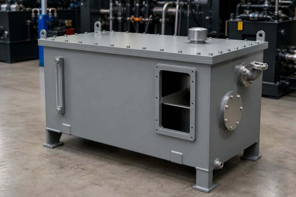
Hydraulic tanks · Volume against pump flow, air space and return-flow velocity, baffles, breathers and fillers
A hydraulic reservoir is the tank that stores a hydraulic system's fluid and lets it shed heat, settle contaminants and release air before the pump draws it again. Ask three things first: what volume the tank holds relative to the total pump flow and fluid type, how much air space it leaves above the fluid, and how returning fluid is slowed and kept away from the pump suction.
Atmospheric and pressurised reservoirs for industrial hydraulic systems and presses, with their baffles, fillers, breathers, level and temperature indicators, strainers and mounting plates. Complete hydraulic power units, accumulators and fuel tanks are outside this page.
CNFX editorial research · Sources checked October 11, 2026 · 4 sources
Darko Lovrec and Ignacijo Biluš of the University of Maribor, in a 2021 Fluid Power conference paper, summarise recommended tank sizes as multiples of all pumps' flow per minute: for industrial mineral-oil systems a minimum of 2.5 and a recommendation of 3–5 times; for industrial HFC and HFD fluids a minimum of 5 and a recommendation of 8 times, because contaminants separate less well; and 1.5–2.5 times for mobile open-loop systems. In all cases they add about 10–15% for air cushion, thermal expansion and unequal cylinder chambers, and note that tanks that are too small cause overheating, faster fluid ageing and cavitation. [1]
Power & Motion explains the traditional rule as three times the rated output of a fixed pump or the mean flow of a variable pump — a 5 gpm pump with a 15 gal reservoir — but quotes the NFPA Recommended Practice ANSI/(NFPA)/T3.16.2 as saying three times had previously been recommended and that design objectives have since changed for space, oil volume and cost. It notes that large accumulators or cylinders, high ambient temperatures and heat from relief-valve flow can all require a larger tank or a heat exchanger. [2]
Editorial calculation: a press with 60 L/min of mineral-oil pump flow needs 180–300 L of fluid at 3–5 times, or 480 L at 8 times with an HFC fluid; adding 10–15% air space gives about 198–345 L of tank for mineral oil. The pump flow is an assumed example. [1]
Give the supplier the pump flows, fluid type, fluid volume swings from cylinders and accumulators, heat load and ambient temperature, heat exchanger if any, components to mount on the lid, available floor space and height, required ports and accessories, surface treatment and cleanliness, and how the tank will be lifted and moved.
02
Detail the tank for air release and clean fluid
Power & Motion lists the reservoir's roles as heat transfer, slowing returning fluid so contaminants settle and air escapes, a baffle separating return fluid from pump suction, air space above the fluid, and room for thermal expansion and drain-back. It calls for additional space of at least 10% of fluid capacity, and notes that NFPA/T3.16.2 requires the maximum fluid capacity to be permanently marked on the top plate. [2]
For small reservoirs it recommends a flow diffuser that slows return fluid to the 1 ft/s figure Power & Motion gives, and an angled screen that gathers small bubbles into larger ones. It asks for two filler openings on opposite sides filling at 5 gpm or more, 30-mesh or finer metal strainer screens, a breather with 40 µm air filtration, a level indicator with high and low marks at each filler, and lift rings or forklift provisions strong enough to move the tank full; magnets in the return path collect ferrous particles. [2] Lovrec and Biluš also list separated suction and return lines with baffle plates, maintenance access and room for system components. [1]
US patent 4,210,176 (J. I. Case Co., filed 14 September 1978, granted 1 July 1980) shows one way to build the return-to-suction separation into a welded rectangular tank: a divider plate welded to the bottom wall and two flat baffle plates sloping down from its top edge split the tank into three compartments — a lower inlet compartment, a lower outlet compartment and an upper compartment that joins them below the normal liquid level. The openings sit next to opposite sidewalls, so returning oil must cross the full width of the tank before reaching the pump outlet, and a single vent tube runs from the highest point of each lower compartment to above the liquid level to release trapped air. The patent states the aim as maximum dwell time, de-aeration and mixing of return oil with the rest of the fluid, and describes a diffuser and strainer screen on the inlet and a breather cap with dip stick on the filler pipe. [3]
Editorial calculation: to slow a 60 L/min return flow (0.001 m³/s) to 1 ft/s (0.3048 m/s), the diffuser needs an outlet area of about 0.001 / 0.3048 ≈ 0.0033 m², the area of a pipe about 65 mm in diameter. 5 gpm is about 18.9 L/min per filler. [2]
Caterpillar's patent application US 2014/0014215 A1 describes a return diffuser assembly for high-velocity, high-pressure return lines: an inlet tube closed at its far end feeds two or more perforated diffuser conduits set at about 60° to about 120° to the inlet-tube axis (right angles in the example), each conduit carrying holes in staggered rows of four holes, a slot for a velocity-reducing plate and an end plate that may carry a pressure release valve. The application states that the holes reduce return velocity, turbulence, foaming and noise and also trap particles ahead of the pump, and that the number of diffusers depends on the flow attenuation and sound reduction required. [4] Editorial note: ask the tank maker whether the return line ends in a screen-type or perforated-tube diffuser, and for its outlet velocity at your peak return flow.
03
A welded-tank fabricator's reservoir range
The listing reviewed is a fabricator of welded hydraulic oil reservoir tanks and frames; ask for the tank volume, wall thickness, internal baffles, ports and surface treatment as built.
04
Baffles, breather, strainers and diffuser inside the tank
Slow return flow; trap iron. [2] Perforated conduits at about 60°–120° to the inlet tube. [4]
Diffuser size; magnets.
05
Capacity, temperature limits and filtration ratings
Lovrec and Biluš supply the capacity multiple and Power & Motion the breather and filler-screen ratings; the material, coating and seal rows carry no sourced value and depend on your fluid.
Field
What it means and published values
Ask the supplier for
Nominal capacity (L)
Example: 3–5 × pump flow per minute for mineral oil, plus 10–15%. [1]
Explore company information and manufacturing capabilities, then discuss the scope of your project with a relevant supplier.
Share this page
Compiled and source-reviewed by the CNFX editorial team.
Each manufacturer above links to the page on that company's own website where the product is listed, with the date we checked it. How we source and review
· Page last updated 13 October 2026
Buyer questions
How big should a hydraulic reservoir be?
Lovrec and Biluš recommend 3–5 times all pumps' flow per minute for industrial mineral-oil systems, plus about 10–15%. [1]
Is the three-times rule still valid?
Power & Motion quotes the NFPA practice as saying three times was previously recommended but objectives have changed for space and cost. [2]
How much air space should a hydraulic tank have?
Power & Motion calls for at least 10% of fluid capacity. [2]
What breather rating should a reservoir use?
Power & Motion specifies 40 µm air filtration. [2]
How can a baffle stop return oil going straight to the pump suction?
US patent 4,210,176 divides the tank into two lower compartments and one upper compartment, with openings at opposite sidewalls so return oil crosses the whole tank, and a vent tube releases air from the lower compartments. [3]
How is a return-line diffuser built inside a hydraulic tank?
Caterpillar's US 2014/0014215 A1 uses an inlet tube feeding two or more perforated conduits set at about 60° to 120° to the tube axis, with holes in staggered rows of four, to cut velocity, turbulence and foaming. [4]
Sources and what still needs a direct check
Sources checked 2026-10-11. Lovrec and Biluš are university researchers summarising sizing guidance in a conference paper; Power & Motion is a trade publication explaining practice and quoting the NFPA recommended practice. The standards themselves govern design. US patent 4,210,176 (J. I. Case Co.) is a primary design document for a three-compartment baffled reservoir, and Caterpillar's patent application US 2014/0014215 A1 is a primary design document for a perforated return diffuser.