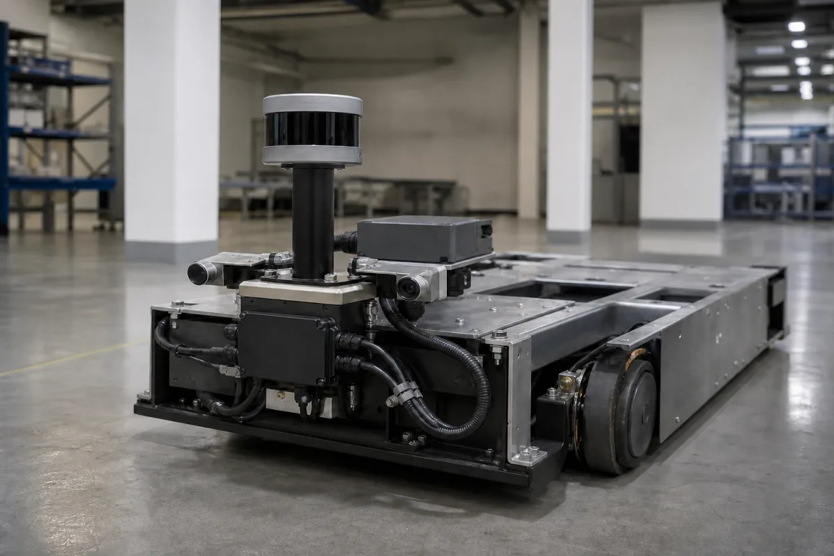
AGV laser navigation system: reflector-based positioning with a rotating laser scanner
Reflector-based laser navigation for AGVs · a rotating laser on a mast measures angles and distances to retro-reflectors and fixes the vehicle's position and heading
An AGV laser navigation system is the positioning subsystem of a laser-guided vehicle: a scanner on a mast above the vehicle sweeps a laser beam through 360°, detects retro-reflective marks fixed on walls, columns and machines, and from the measured angles and distances to known reflectors computes where the vehicle is and which way it faces. The vehicle computer combines that position with odometry to steer along a virtual path. Buying one means planning the reflector layout as much as choosing the scanner.
Reflector-based laser navigation subsystems for AGVs and laser-guided vehicles: the navigation scanner, the reflector layout and mapping, and the interface to the vehicle controller. Complete AGV systems with their vehicles, traffic control, charging and safety are covered on the Automated guided vehicle system (AGVS) page; general-purpose LiDAR sensors are covered on the LiDAR sensor page.
CNFX editorial research · Sources checked October 12, 2026 · 3 sources
Fix position and heading from the angles to three known reflectors
The method was patented in the 1980s by INIK Instrument och Elektronik, with later assignment records naming NDC Automation: a laser beam on the truck is swept round by a rotating mirror at a constant speed of the order of 2 or 3 revolutions per second, an angle meter records the bearing to each reflector it passes, and the position and direction of the truck are calculated by trigonometry from the angles to three fixed reflectors that it "sees" from where it stands. [3]
The patent describes the reflectors as simple and inexpensive reflecting tape, fixed directly to walls or objects or wound on vertical pins about 20 mm in diameter, with some vertical extent and a dark background behind them. [3]
A current navigation scanner, SICK's NAV350, works the same way at higher resolution: a 905 nm class 1 laser scanning 360° at 8 Hz with 0.25° angular resolution, detecting reflectors from 0.5 to 70 m, storing up to 12,000 reflectors that can be split into up to 320 layers, and recommending reflector stripes at least 80 mm wide or cylinders at least 80 mm in diameter. [1][2]
On switching to navigation, the NAV350 first matches the pattern of measured reflectors against the stored layout; this needs the vehicle to be stationary and at least three reflectors in view, and SICK notes that, depending on the number of reflectors measured and stored, it can take a few seconds. It then tracks reflectors inside an identification window around each expected position (300 mm by default, configurable from 100 to 2,000 mm) and uses the 4 to 8 best distributed reflectors for each fix. If it loses position it estimates one from the reported speeds for at most 3 m before stopping. [2]
02
Lay out reflectors so at least three are visible from every point on the route
SICK requires the reflector layout to keep at least three reflectors visible to the scanner from every position, including when the radius of action is restricted or sectors are muted; if only two remain in a restricted radius the device falls back to its full radius. [2]
Reflectors must be at least 300 mm away from highly reflective objects such as windows, stainless-steel casings or metal pipes, which can otherwise be read as reflectors, and SICK recommends placing reflectors at docking stations such as pallet transfer points and, on bends, within the restricted radius of action, because nearer landmarks are measured more accurately. Its example of a restricted radius of action uses r min = 500 mm and r max = 15,000 mm. [2]
Where a raised load hides part of a reflector, up to four angular sectors can be muted so that half-covered reflectors are not used; the layout must still leave three reflectors visible outside the muted sectors. Reflector positions are either measured and stored in the device or taught in by its mapping function, in an absolute coordinate system with a defined zero point. [2]
Ask the supplier for a reflector layout drawing showing the visible reflectors at each pick-up and drop-off point and on each bend, and for the mapping and survey method.
03
Check position accuracy against reflector distance, and feed the scanner the vehicle's speed
SICK gives the NAV350's position accuracy as ±4 mm to ±25 mm depending on the average reflector distance, with ±0.1° angular accuracy; the datasheet lists ±4 mm positioning accuracy and typical systematic errors of ±10 mm on reflectors and ±15 mm on contours, depending on environmental conditions. [1][2]
Editorial calculation: a ±0.1° heading error displaces a point 10 m ahead by about ±17.5 mm (10,000 mm × tan 0.1°), which is why heading accuracy matters as much as position accuracy for long straight runs and fork entry.
The vehicle computer should send its speed and rotational speed to the scanner, transformed to the scanner's position; the scanner uses them to correct for motion during a scan. Without speed data the scanner estimates speed itself, which SICK says suits low accelerations and testing only. [2] Editorial calculation: at an assumed 1.5 m/s, a vehicle travels about 188 mm between two 8 Hz position updates.
With each position, the NAV350 reports a measurement quality as the standard deviation, in millimetres, of the detected against the stored reflector positions; SICK leaves it to the system integrator how strongly that position corrects the odometry. The unit runs on 24 V DC ±15% at 36 W, is IP65, weighs 2.4 kg, operates from 0 to 50 °C, and SICK states that it does not constitute a safety component as defined by machinery safety legislation. [1][2]
04
Data for an AGV laser navigation enquiry
Paste it into your enquiry below or into an email to a maker, then replace every bracket.
Vehicles: [type; maximum speed; mast height available]
Route: [layout drawing; pick-up and drop-off points; bends]
Accuracy: [position and heading tolerance at load transfer]
Reflectors: [flat stripes or cylinders; mounting surfaces; survey or teach-in]
Environment: [indoor; temperature; reflective surfaces; loads that block view]
Interface: [Ethernet or serial; vehicle controller; speed data]
Safety: [personnel-protection devices on the vehicle]
Explore company information and manufacturing capabilities, then discuss the scope of your project with a relevant supplier.
Share this page
Compiled and source-reviewed by the CNFX editorial team.
Each manufacturer above links to the page on that company's own website where the product is listed, with the date we checked it. How we source and review
· Page last updated 13 October 2026
Buyer questions
How many reflectors does an AGV laser navigator need to see?
At least three from every position; SICK's NAV350 needs three in view to start and selects the 4 to 8 best distributed reflectors for each position fix. [2][3]
How accurate is reflector-based laser navigation?
SICK gives ±4 mm to ±25 mm position accuracy depending on average reflector distance, and ±0.1° angular accuracy, for the NAV350. [2]
Can the navigation scanner also protect people?
No. SICK states the NAV350 is not a safety component as defined by machinery safety legislation. [1]
Sources and what still needs a direct check
Sources checked 2026-10-12. Scanner data come from SICK's NAV350 datasheet and operating instructions (2024-11 edition); the measuring principle from US patent 4,811,228. Values apply to the device named.