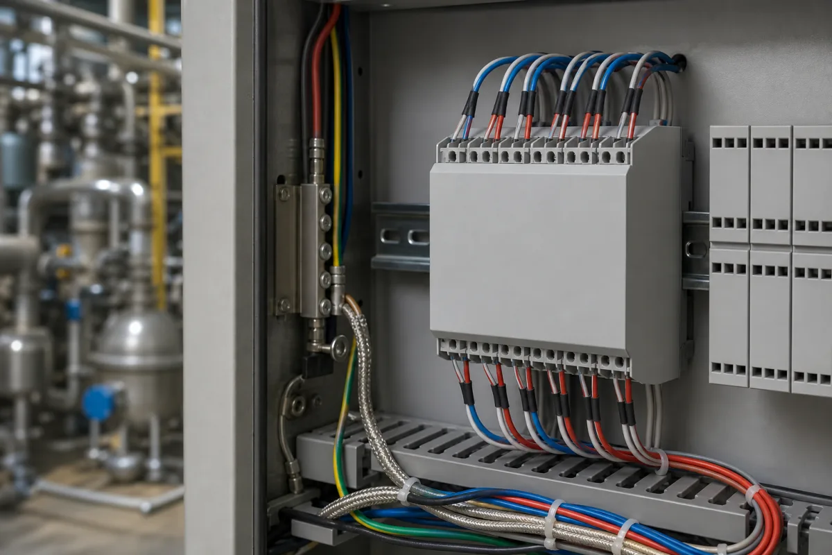
Temperature input module for RTD and thermocouple sensors (4-channel Pt100 and thermocouple input card for PLC and EtherCAT remote I/O)
RTD and thermocouple input modules · Pt100 tolerance classes and 2-, 3- or 4-wire lead compensation, thermocouple types and cold-junction compensation, resolution against accuracy in °C
A temperature input module is a PLC or remote I/O module whose channels connect straight to temperature sensors: platinum or nickel resistance thermometers (RTDs) or thermocouples. Instead of reading a 4–20 mA or 0–10 V signal from a transmitter, it excites the RTD or measures the thermocouple's millivolts itself, compensates the lead wires or the cold junction, linearises the sensor curve and passes a temperature value to the controller. The buying questions are which sensor types and wiring it accepts, how lead resistance and the cold junction are handled, its accuracy in degrees for your sensor and range, and its isolation.
Direct-sensor temperature input modules and terminals for RTDs (Pt100, Pt1000, Ni) and thermocouples in PLC racks and fieldbus remote I/O, including their linearisation, lead-wire and cold-junction compensation. Analog input cards for voltage and current signals, including mixed cards that also accept an RTD or thermocouple as one of their input types, are covered with their input reference and common-mode limits on the Analog input module for PLC, remote I/O and data acquisition page; this page is limited to modules whose channels are built only for direct sensor connection. 24 V DC discrete input cards are covered on the Digital input module page; machine-tool CNC I/O on the CNC input/output module page. DIN-rail trip units that switch a relay at a temperature limit are covered on the Temperature alarm module page; chassis DAQ cards and serial acquisition modules on the Data acquisition module page; controllers with bus couplers on the PLC controller with fieldbus remote I/O page; relay output terminals on the Relay output module page. Temperature transmitters, Pt100 probe assemblies and stand-alone temperature controllers are separate products.
CNFX editorial research · Sources checked October 12, 2026 · 3 sources
Pt100 inputs: 2-, 3- or 4-wire connection and the lead resistance each one leaves in the reading
Texas Instruments' guide to RTD measurement sets out the three wiring options. With two wires, the lead resistances cannot be separated from the RTD resistance, so they add an error; two-wire is the least accurate and is used when accuracy is not critical or leads are short. With three wires, lead resistance can be cancelled, but the compensation assumes the lead resistances match. With four wires, excitation flows through one pair and the RTD voltage is sensed on the other, so the lead resistance contributes no error. [1]
The module itself converts resistance to temperature. TI gives the Callendar-Van Dusen equation with the IEC 60751 coefficients for a Pt100 (R0 = 100 Ω at 0 °C; A = 3.9083×10⁻³, B = −5.775×10⁻⁷, C = −4.183×10⁻¹²), and notes that a straight-line fit from −200 to 850 °C would be off by more than 16 Ω, which is why the curve is computed or looked up rather than treated as linear. [1]
Editorial calculation: near 0 °C a Pt100 changes by about 100 Ω × 3.9083×10⁻³ ≈ 0.39 Ω per °C. Assuming two copper leads of 10 m each at 0.5 mm² (copper about 0.0172 Ω·mm²/m), the loop adds about 0.69 Ω, which a 2-wire input would read as roughly 1.8 °C too high. On a 3-wire input the error cancels to the extent the leads match, and on a 4-wire input the leads contribute none, per the wiring descriptions above.
EDATEC's EtherCAT temperature module accepts 2-, 3- and 4-wire RTD connections, defaulting to 3-wire, and lists Pt100, Pt200, Pt500, Pt1000 and Ni20 sensors, with ranges of −200 to +800 °C for the platinum types and −79 to +309 °C for the nickel type. [3]
State the RTD type (Pt100, Pt1000, Ni), the number of wires at the sensor, the lead length and cross-section, and whether the module must detect a broken or shorted sensor.
02
The sensor's IEC 60751 class adds to the module's error
A module accuracy figure covers the electronics; the RTD has its own tolerance. TI's table of tolerance classes shows the error each grade allows at 100 °C. [1]
TI notes that the temperature range over which each class applies narrows for the tighter classes and depends on the sensor construction, and that the North American ASTM E1137 grades A and B are defined differently. [1]
Editorial calculation: at 200 °C a Class B Pt100 is allowed ±(0.3 + 0.005 × 200) = ±1.3 °C. Paired with a module rated at ±1 °C, such as EDATEC's [3], the measurement chain could be off by up to about 2.3 °C in the worst case, or about 1.6 °C if the two errors are combined as independent (root-sum-square). A loop that has to hold a tighter band needs a better sensor class, a better module, or both.
Thermocouple inputs: microvolts per degree and cold-junction compensation at the terminals
TI's thermocouple guide tabulates the output of types J, K, T, E and S and their Seebeck coefficients at 0 °C. A thermocouple input module has to resolve signals of this size. [2]
The thermocouple voltage depends on the difference between the hot junction and the cold junction, where the thermocouple wires meet the module's copper terminals. TI describes cold-junction compensation as measuring that block's temperature with a diode, thermistor or RTD, converting it to the equivalent thermocouple voltage, adding it to the measured voltage, and only then converting the sum to temperature; because the curves are non-linear, the cold-junction temperature cannot simply be added in degrees. TI also notes that air currents can disturb the block and an enclosure may be needed. [2]
EDATEC's thermocouple module accepts types K, J, T, E, N, S, R, B and C, with type K the default over −100 to +1,370 °C. [3] Editorial calculation: at type K's 39.48 µV/°C, the module's 0.1 °C resolution corresponds to about 4 µV at the terminals; for type S at 10.19 µV/°C, the same 0.1 °C is about 1 µV, which is why the noble-metal types are harder to read precisely.
State the thermocouple type, whether extension or compensating cable runs to the module, where the cold junction sits (module terminals or an external block), and the cabinet temperature swing.
04
Reading a temperature module data sheet: channels, resolution versus accuracy, isolation
EDATEC sells its EtherCAT temperature modules as two separate 4-channel parts, ED-EIO4RTD for RTDs and ED-EIO4TC for thermocouples, each with a per-channel LED that flashes while a signal is detected and is off with no input. [3]
Resolution and accuracy are separate figures: the module reports in 0.1 °C steps, but the stated accuracy is ten times wider. Editorial note: where channels are not isolated from one another, as here, ask how the module handles sensors at different potentials, for example grounded-junction thermocouples on separate machine parts.
Up to 32 modules cascaded behind a coupler without extra power supply [3]
Ask for accuracy per sensor type and range (not one figure for all), the cold-junction error for thermocouple modules, conversion time per channel, sensor-break detection, and channel-to-channel isolation.
05
Data for a temperature input module quotation
Paste it into your enquiry below or into an email to a maker, then replace every bracket.
Sensors: [RTD type and class, or thermocouple type; number per module]
Wiring: [2-, 3- or 4-wire; lead length and cross-section; extension cable]
Range and accuracy: [temperature range per channel; accuracy needed in °C]
Cold junction: [at module terminals or external; cabinet temperature range]
System: [PLC or coupler; EtherCAT, PROFINET or other; update time]
Isolation and diagnostics: [field-to-bus; channel-to-channel; broken-sensor detection]
EDATEC lists separate 4-channel RTD and thermocouple modules for its EtherCAT remote I/O.
EDATEC
Manufacturing site to be confirmed for the order
Lists EtherCAT temperature input modules ED-EIO4RTD (4-channel RTD) and ED-EIO4TC (4-channel thermocouple), with Pt100 to Pt1000, Ni20 and K, J, T, E, N, S, R, B and C sensor support.
Explore company information and manufacturing capabilities, then discuss the scope of your project with a relevant supplier.
Share this page
Compiled and source-reviewed by the CNFX editorial team.
Each manufacturer above links to the page on that company's own website where the product is listed, with the date we checked it. How we source and review
· Page last updated 13 October 2026
Buyer questions
Why use a 3- or 4-wire RTD connection?
TI explains that a 2-wire connection leaves the lead resistance in the reading, a 3-wire connection cancels it if the leads match, and a 4-wire connection senses the RTD without lead error. [1]
What is cold-junction compensation on a thermocouple module?
The module measures the temperature where the thermocouple meets its terminals, converts it to a thermocouple voltage, adds it to the measured voltage and converts the sum to temperature. [2]
Does 0.1 °C resolution mean 0.1 °C accuracy?
No. EDATEC's modules list 0.1 °C resolution and ±1 °C accuracy, and the sensor's own tolerance class adds to that. [3][1]
How accurate is a Class B Pt100?
TI's table gives ±(0.3 + 0.005·|T|) °C for IEC Class B, ±0.8 °C at 100 °C. [1]
Sources and what still needs a direct check
Sources checked 2026-10-12. Texas Instruments' application notes explain RTD and thermocouple measurement from the sensor side; EDATEC describes its own EtherCAT temperature modules.