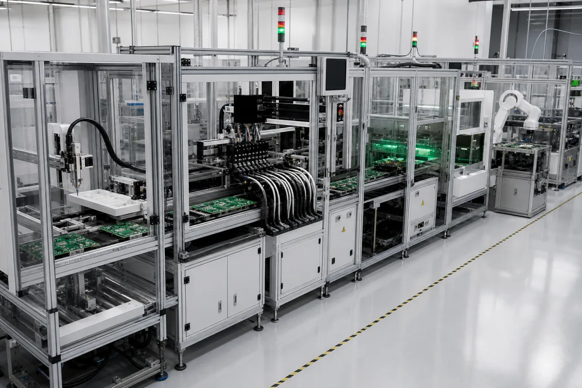
Modular PCB assembly system: docking back-end cells for press-fit, odd-form and screwing stations after the SMT line
Back-end assembly after the SMT line · stand-alone cells for press-fit, odd-form parts and screwing that dock to each other through SMEMA or IPC-HERMES-9852, and what each cell's footprint, force and changeover figures mean for a communication-equipment board line
Press-fit connectors and other parts that are not reflow-soldered are fitted to communication-equipment boards after the SMT line. A modular PCB assembly system does that work in self-contained cells: each one has its own frame, guarding, conveyor section and controller, docks to its neighbours, and can be moved, swapped or duplicated when the product changes. Three things decide whether such a line works: how the cells hand boards and board data to each other, what each process cell can do (force, part count, board size) and how fast it changes over to a new board type.
Modular back-end PCB assembly systems: stand-alone docking cells for press-fit, odd-form placement, screwing and similar post-SMT operations, and the board data they take from SMEMA or IPC-HERMES-9852 handovers. Edge-belt link, buffer, flip and lift conveyor modules and the choice between a SMEMA handshake and Hermes data are covered on the PCB conveyor system page; lines of loaders, paste printers, placement machines, reflow ovens and inspection are covered on the Automated SMT assembly line page and single placement machines on the SMT pick-and-place machine page; lines that add radial and axial insertion and selective or wave soldering on the Automated printed circuit board assembly line for mixed SMT and through-hole boards page; coating cells on the Automated conformal coating system page.
CNFX editorial research · Sources checked October 12, 2026 · 3 sources
Press-fit cells: 30 kN in an 850 × 1000 mm Baumann cell against 7 or 10 kN inline in IPTE's FlexPresser II
Baumann's pressfit cell for connector strips and PCBs is built on its lean|box modular platform, sized from 600 × 600 mm to 1400 × 1400 mm, with the switch cabinet in the cell, 400 V 16 A and 6 bar supplies, a 15-inch touchscreen and an MES connection over SECS/GEM. Its configuration example is an 850 × 1000 mm cell with 30 kN maximum pressing force, 30 to 150 pins, and pin testing on boards from 50 × 30 mm to 200 × 100 mm. [2]
Baumann's cell feeds and presses on separate stations of a rotary table with exchangeable holders, which it says helps cycle time; a force- and stroke-monitored servo press does the pressing, a pin check in the pressing station contacts the connector to confirm the pins, and a protrusion check before pressing is optional. A type change takes one minute through the visualisation and a mechanical adapter change. Options include separate loading and unloading stations, fail-part sorting, chaku-chaku handling and pin height control by AOI. [2]
IPTE's FlexPresser II works inline instead: pins or connectors come from tray, stick or bowl feeders on a standard interface, the pressing runs up to 7 kN (10 kN as an option) with way and force control programmed from CAD data, a support lift unit limits stress on the board during insertion, and product-specific grippers are exchanged automatically from a gripper bank, with a four-gripper tool magazine and fiducial-based position correction as options. [3]
Editorial calculation: Baumann's lean|box range runs from 0.36 m² (0.6 × 0.6 m) to 1.96 m² (1.4 × 1.4 m), with the 850 × 1000 mm example at 0.85 m². If the 30 kN maximum were spread evenly over the 150-pin maximum, each pin would see 200 N; the actual per-pin force depends on the press-fit pin design and is a question for the connector maker. [2]
Give each press-fit supplier the connector part numbers, pin count and press-in force per pin, board size and thickness, support requirements under the board, and target changeover time between board types.
02
What an assembly cell reads from the board ahead of it: Hermes failed-board and flipped-board flags, product type and clearance heights
A back-end cell that presses connectors or fits odd-form parts acts on boards it did not build, so the useful question is what it is told about each board on arrival. The Hermes protocol, written to replace the electrical SMEMA interface of IPC-SMEMA-9851, sends that with the board handover. [1]
Board IDs are globally unique identifiers (GUIDs, 36 bytes) generated by the first machine in a consecutive row of Hermes machines. Its BoardAvailable message carries that BoardId and the MachineId that created it (minimum supported length 80 bytes), a FailedBoard flag (0 unknown, 1 good, 2 failed), a FlippedBoard flag (0 unknown, 1 top side up, 2 bottom side up), and optionally a ProductTypeId, top and bottom barcodes (minimum supported length 254 bytes), board length, width and thickness in millimetres, the upstream machine's preferred conveyor speed in millimetres per second and top and bottom clearance heights. [1]
The specification adds that when FlippedBoard is 2 the top barcode faces downwards and the bottom barcode upwards, and the same swap applies to the clearance heights. Editorial note: these fields are what a press-fit cell would need to pass over a board flagged as failed upstream, know which side faces up, and pick its program by product type; a cell that only has the SMEMA handshake has to read the board itself. IPTE's FlexPresser II, for example, takes the panel into its work position via a SMEMA interface, with a 1D/2D code reader as an option. [1][3]
List every cell in the planned line with its interface (SMEMA, Hermes and version), lane count and the board data each cell needs from upstream; ask each supplier which Hermes messages and optional fields its cell sends and uses.
03
What each press-fit cell needs fixed before quotation: force, pins, board size, supplies and controller
Explore company information and manufacturing capabilities, then discuss the scope of your project with a relevant supplier.
Share this page
Compiled and source-reviewed by the CNFX editorial team.
Each manufacturer above links to the page on that company's own website where the product is listed, with the date we checked it. How we source and review
· Page last updated 13 October 2026
Buyer questions
What does IPC-HERMES-9852 add over SMEMA?
Hermes replaces the electrical SMEMA handshake with TCP/IP messages that carry a unique board GUID, the creating machine's ID, failed-board and flipped-board flags, barcodes, board dimensions and preferred conveyor speed. [1]
How much force does a press-fit cell provide?
Baumann's configuration example lists 30 kN for 30 to 150 pins; IPTE's FlexPresser II presses with 7 kN, or 10 kN as an option, and takes boards over a SMEMA interface; Hermes flags tell a cell whether a board arrives failed or flipped. [2][3]
How fast can a press-fit cell change board type?
Baumann states a type change within one minute via the visualisation and a mechanical adapter change; IPTE's FlexPresser II exchanges product-specific grippers automatically. [2][3]
Sources and what still needs a direct check
Sources checked 2026-10-12. Board-data fields come from the public Hermes Standard specification draft (version 1.0.4); press-fit cell figures from Baumann's pressfit product sheet and IPTE's FlexPresser II page.